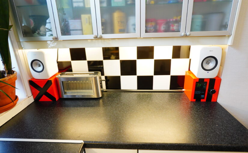
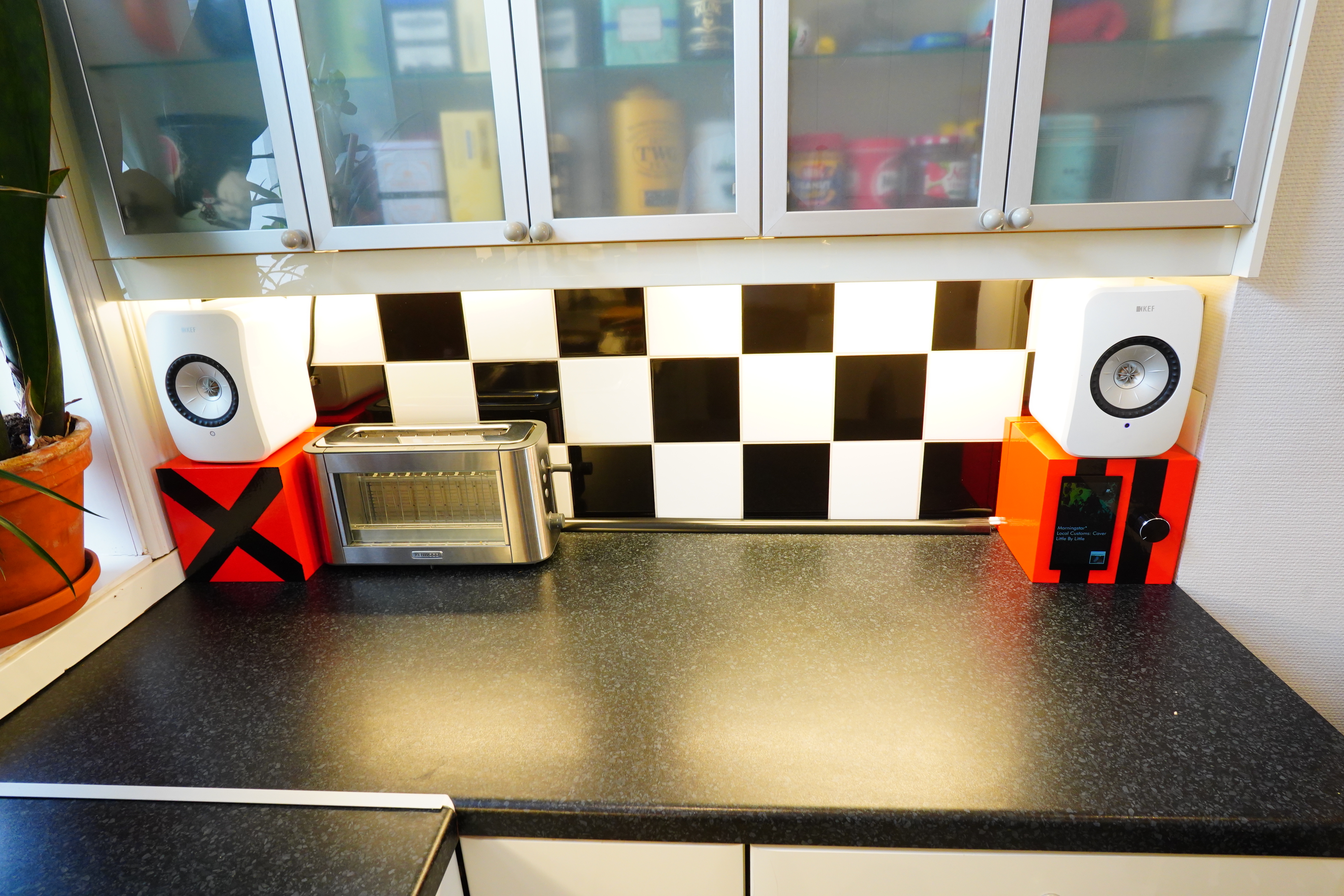
I used to have a all-in-one computer on this kitchen bench, because I thought it would be useful to use to look up recipes and stuff. But I never used it, so half a year ago I downsized to the two boxes you see above. The one to the right has an Emacs-based music player, which is all I thought I needed.
But I forgot how useful it was to have the time and date in the kitchen: The time to say how long to cook things, and the date to throw away spoiled goods.
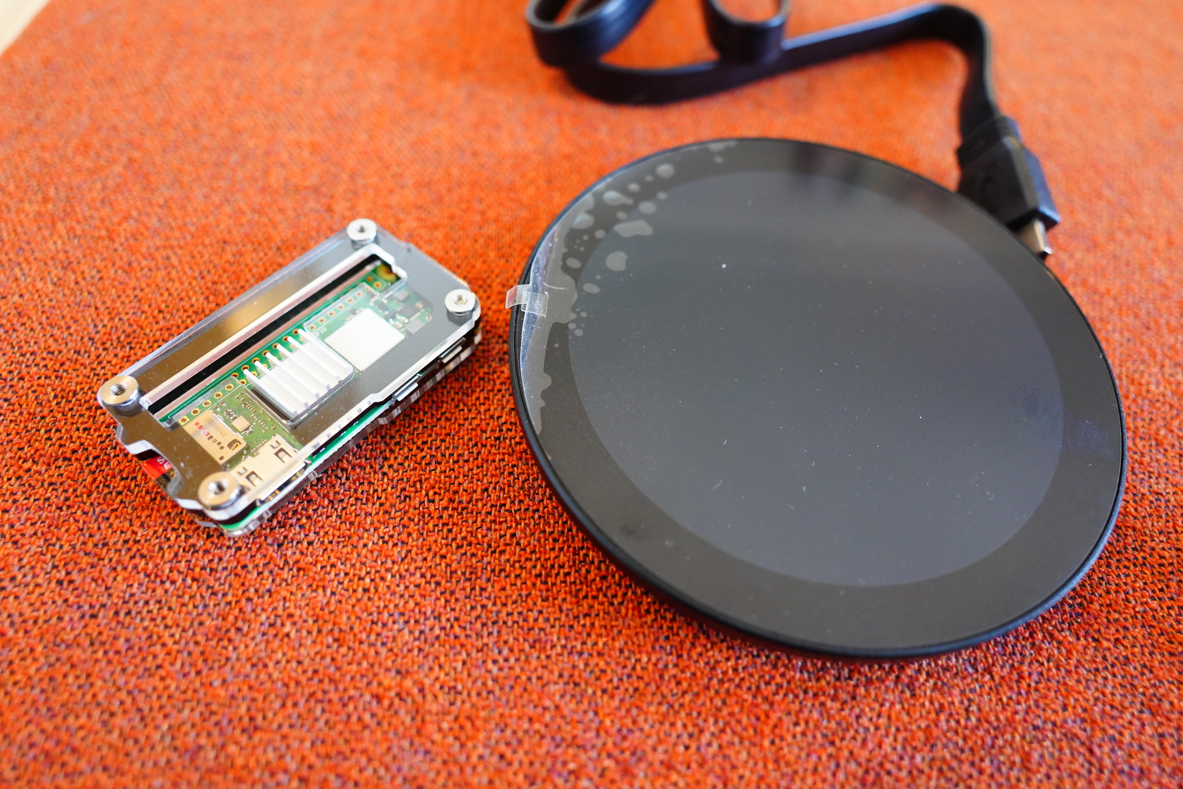
I could be sensible and just buy a clock, or I could cobble together a mess of Raspberry Pis, Emacsen and lots of wifi, so of course I bought a Pi Zero 2 W and a round screen and started hacking.
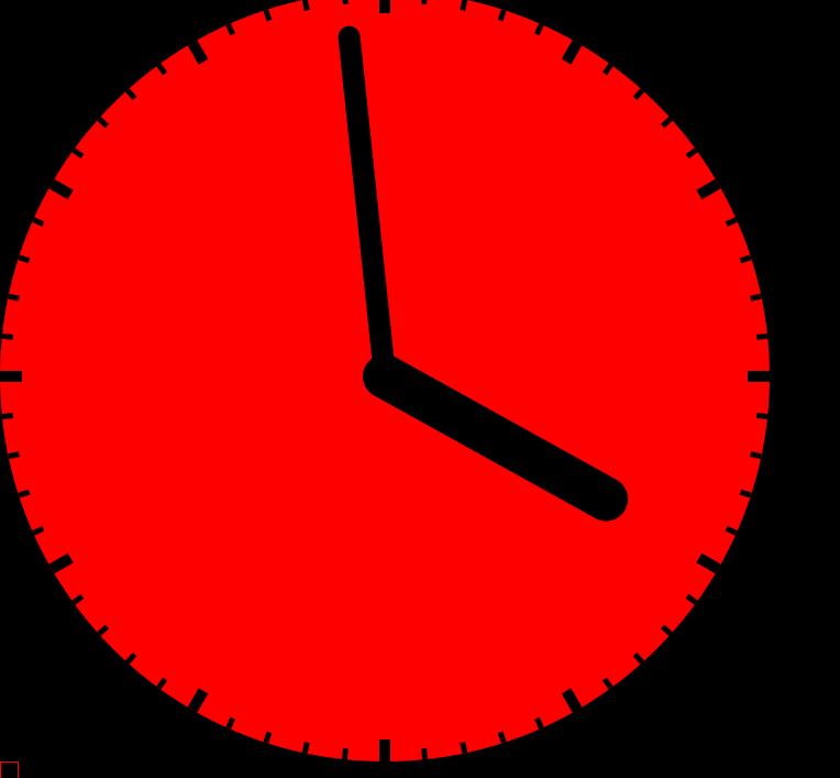
But what should the clock look like?
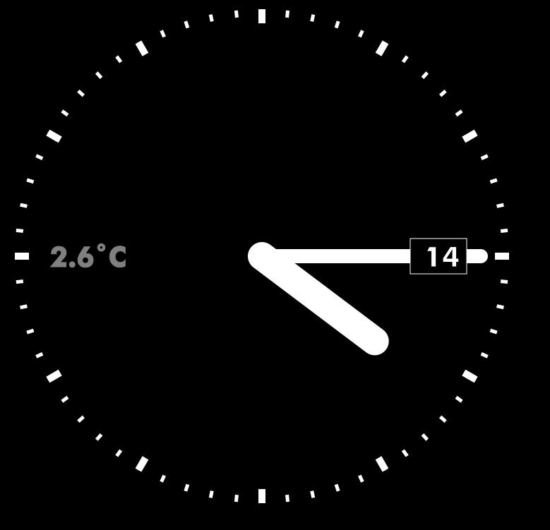
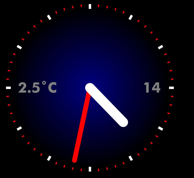
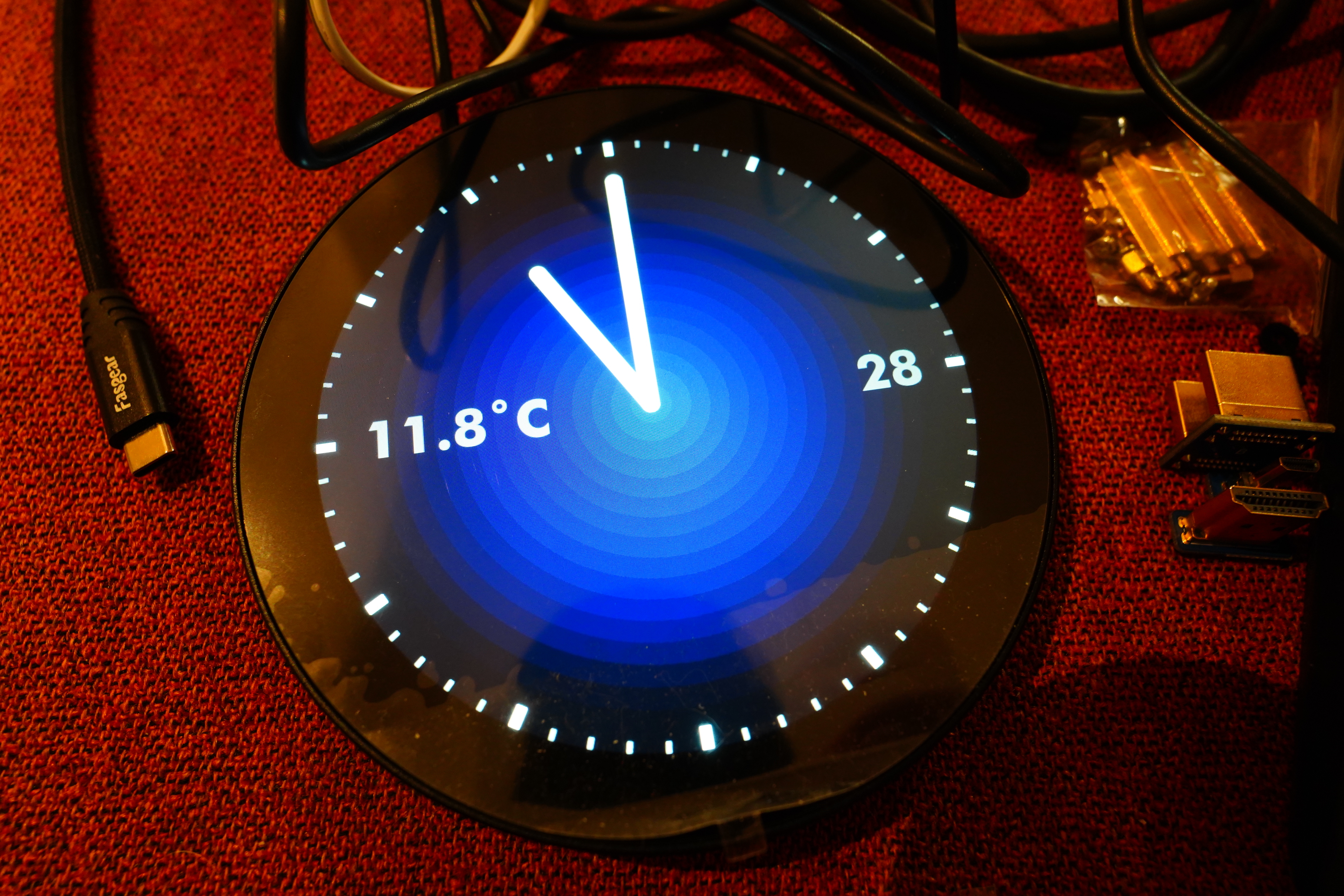
I’m kinda averse to using colours for designs, but it’s a shame to THROW AWAY ALL THOSE MILLIONS OF COLOURS and just go for black and white, eh?
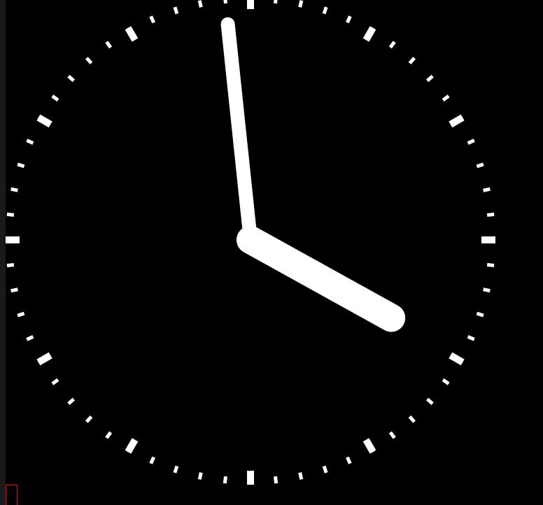
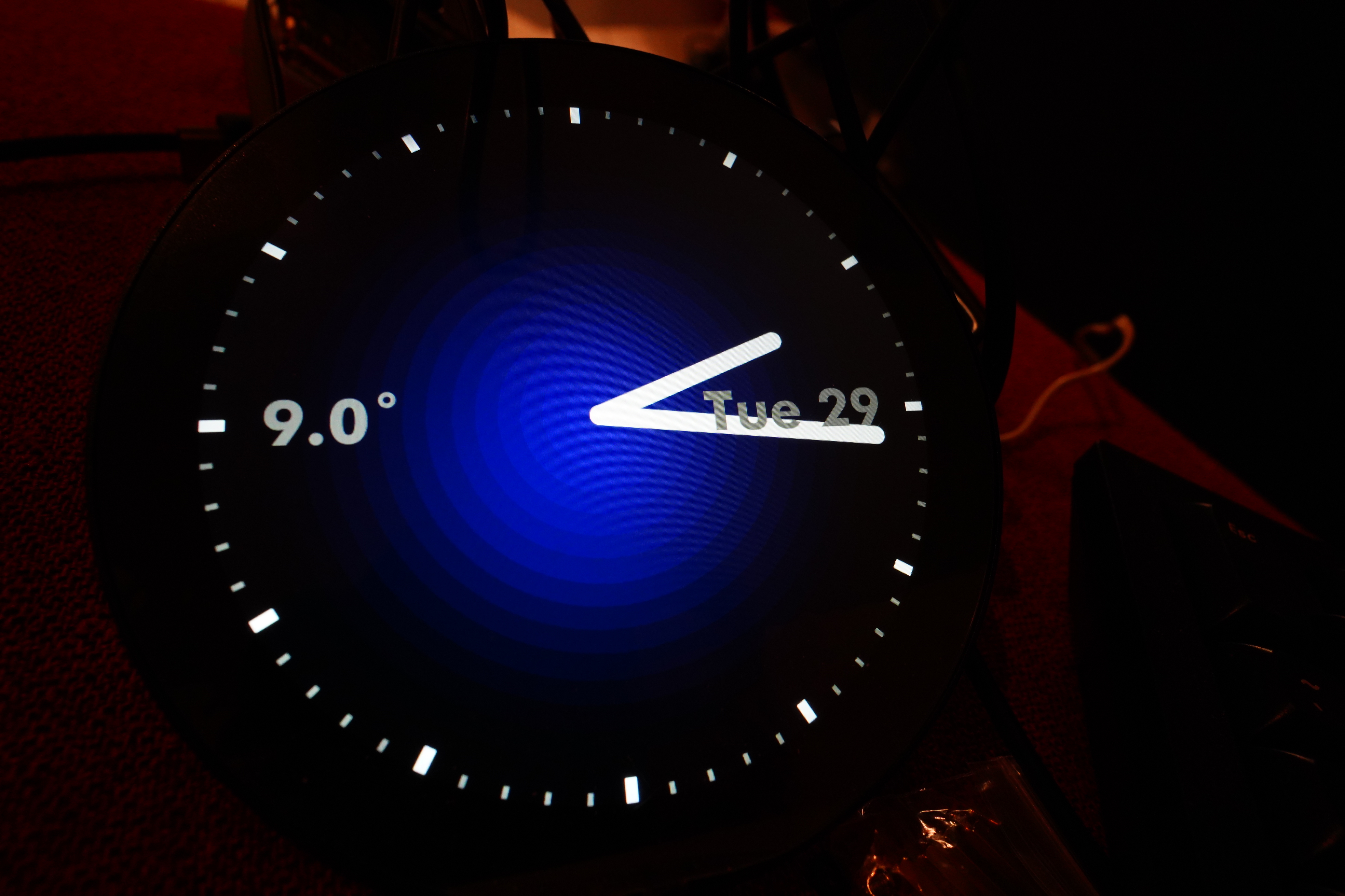
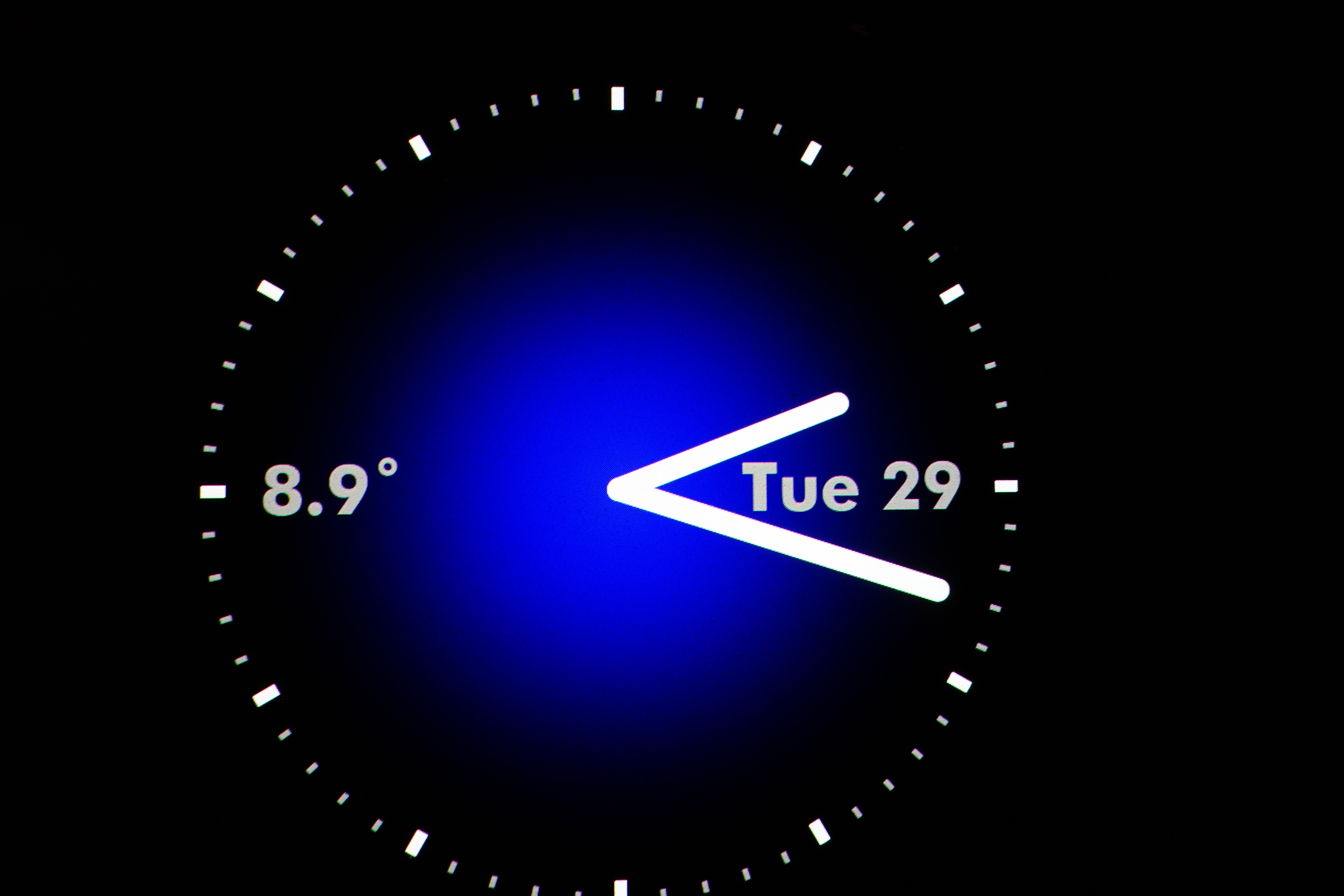
But you gotta admit that simple looks better.
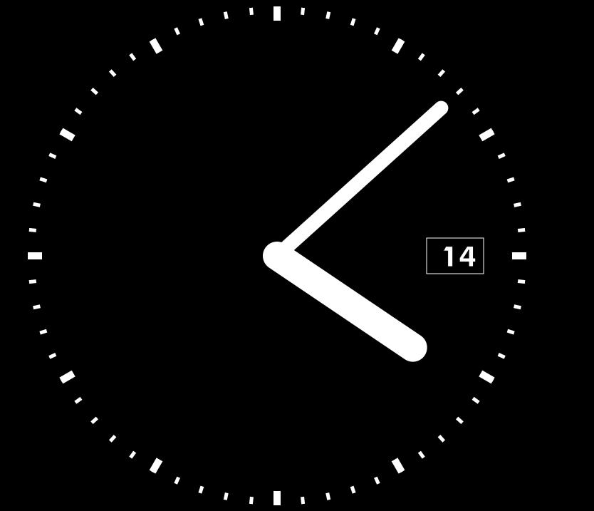
Oh, yeah, the date…
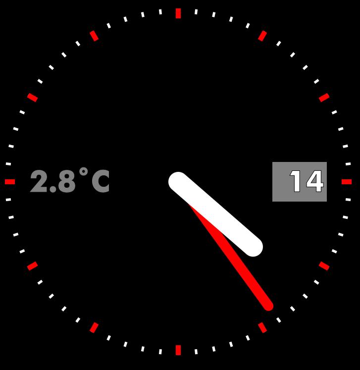
Eh… Oh yeah, I also wanted it to display the outdoors temperature (I’ve got a Weathergoose hanging out the window).
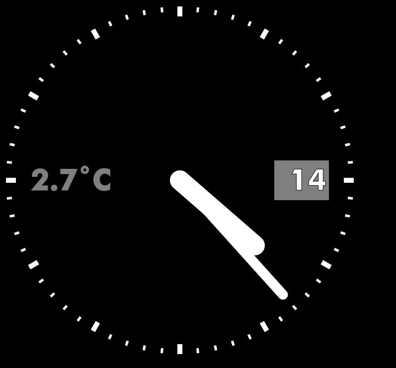
Eh? Eh?
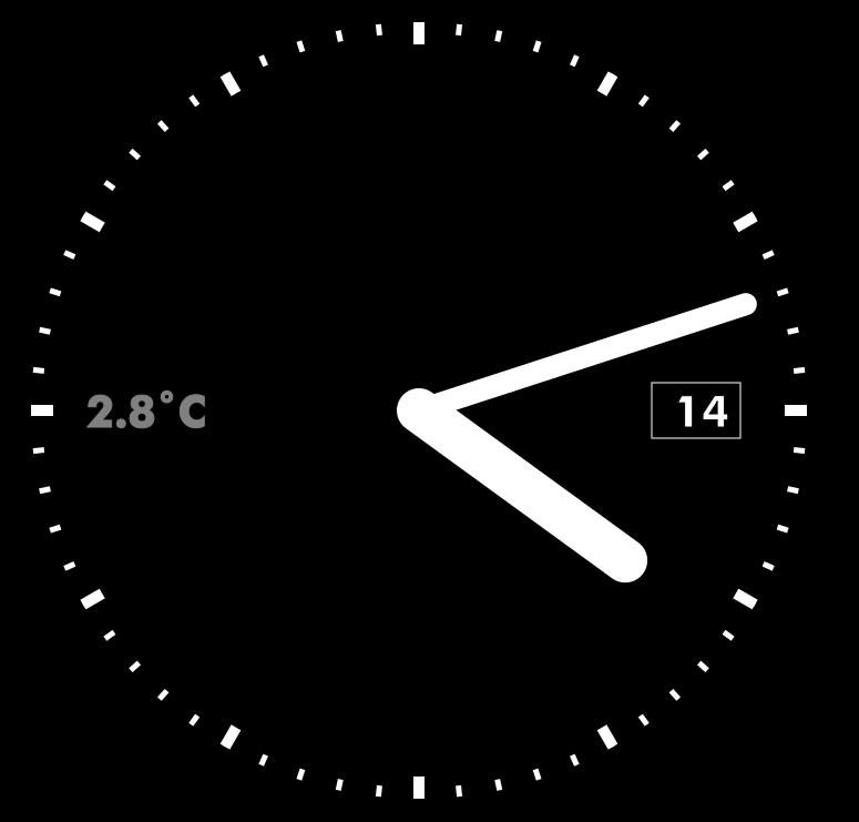
Eh?
Eh?
Oh well, I don’t know. In any case, there’ll be virtually no code running on the Pi, because it’s just 512MB and I’m using Emacs to generate SVGs to make the clocks. So it’s generating these on a server and pushing them to the Pi ahead of time via ssh (i.e., it’s generating the next minute), and then once a minute, the Pi changes the display. (It doesn’t display the seconds, you see.)
Anyway, this means that I can tweak the look endlessly on the server, which I, er, probably will do.
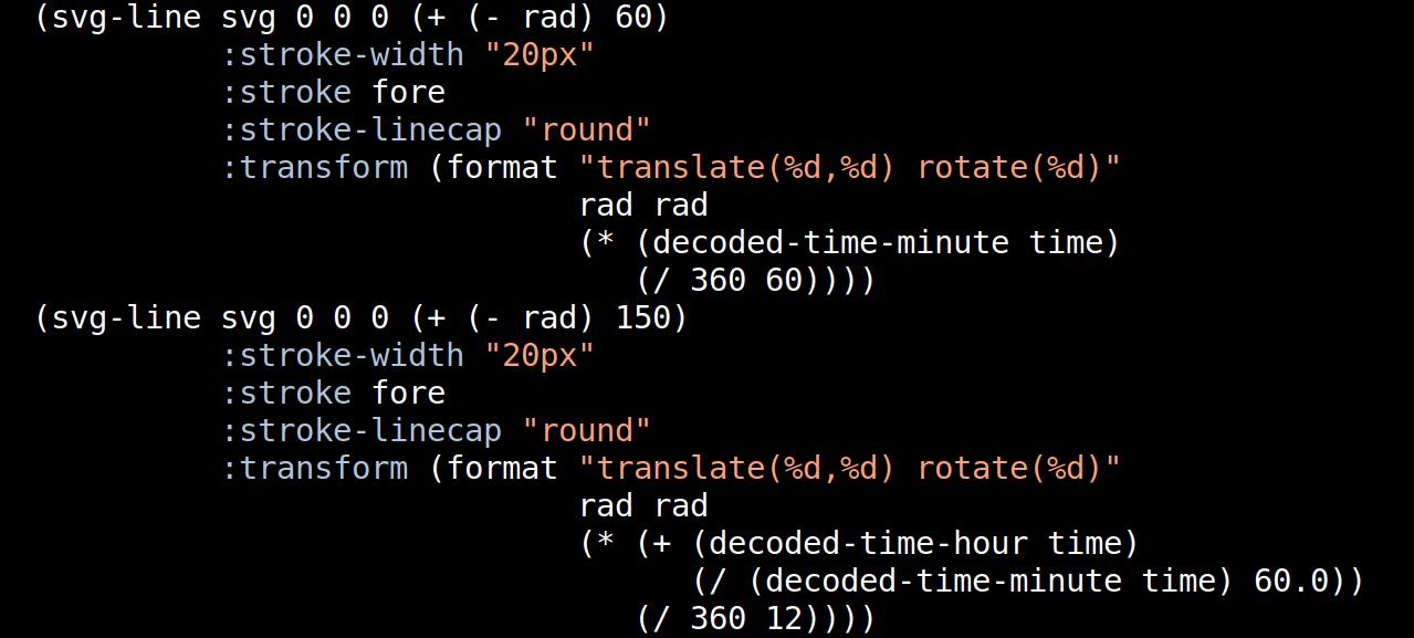
(Is this the right way to calculate the minute and hour hands, by the way? Hm…)
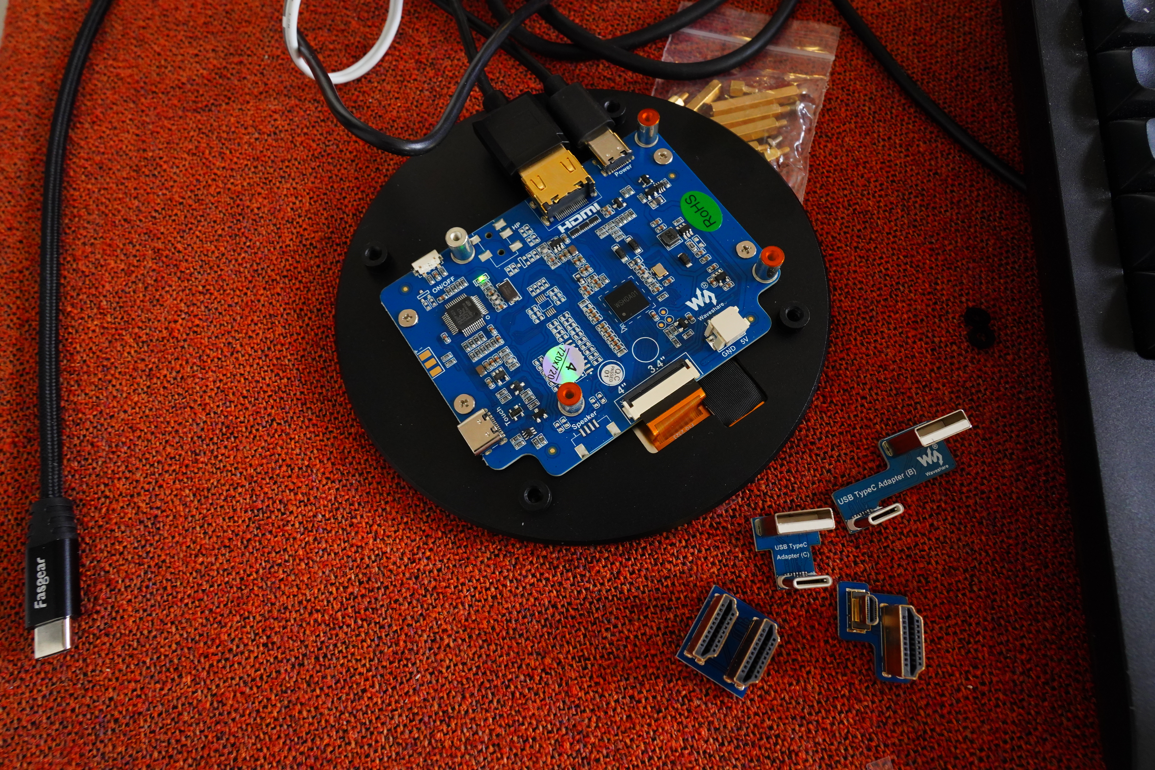
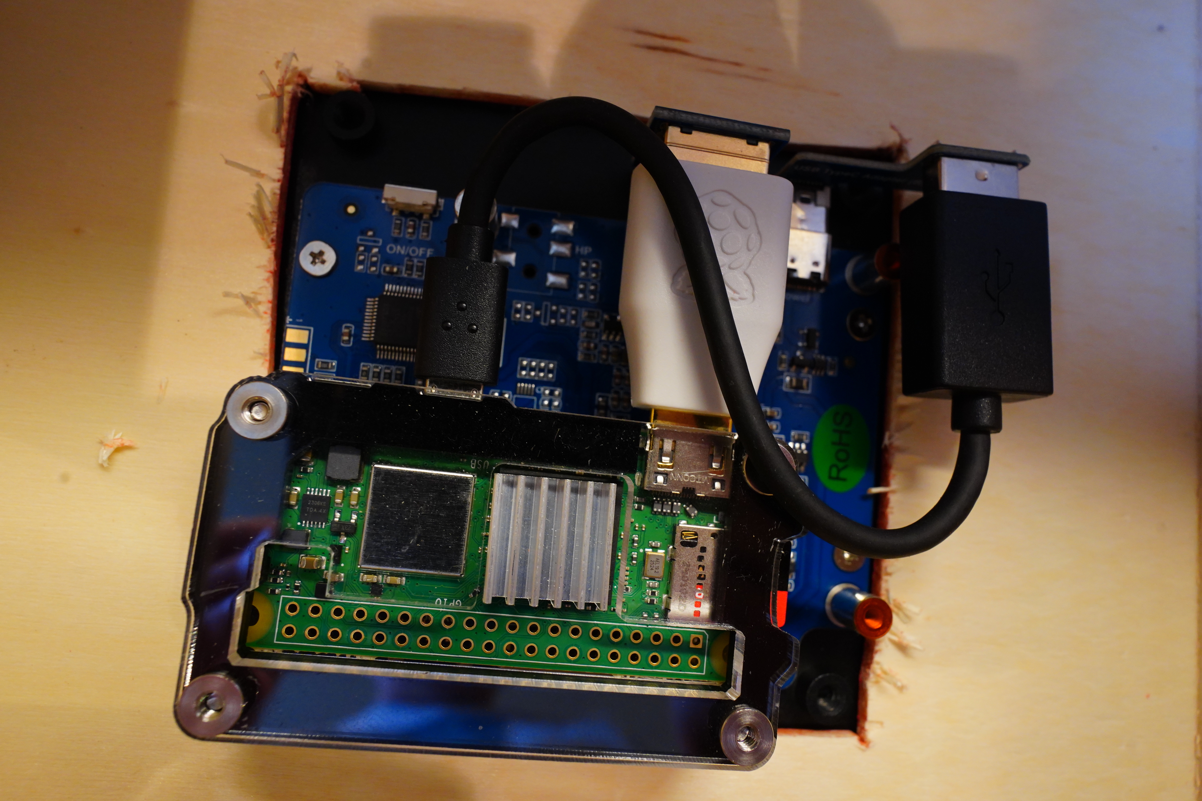
I got this stupid case for the Pi… so many tiny parts.
After procrastinating for half a year, I’m now actually going to build the clock today!
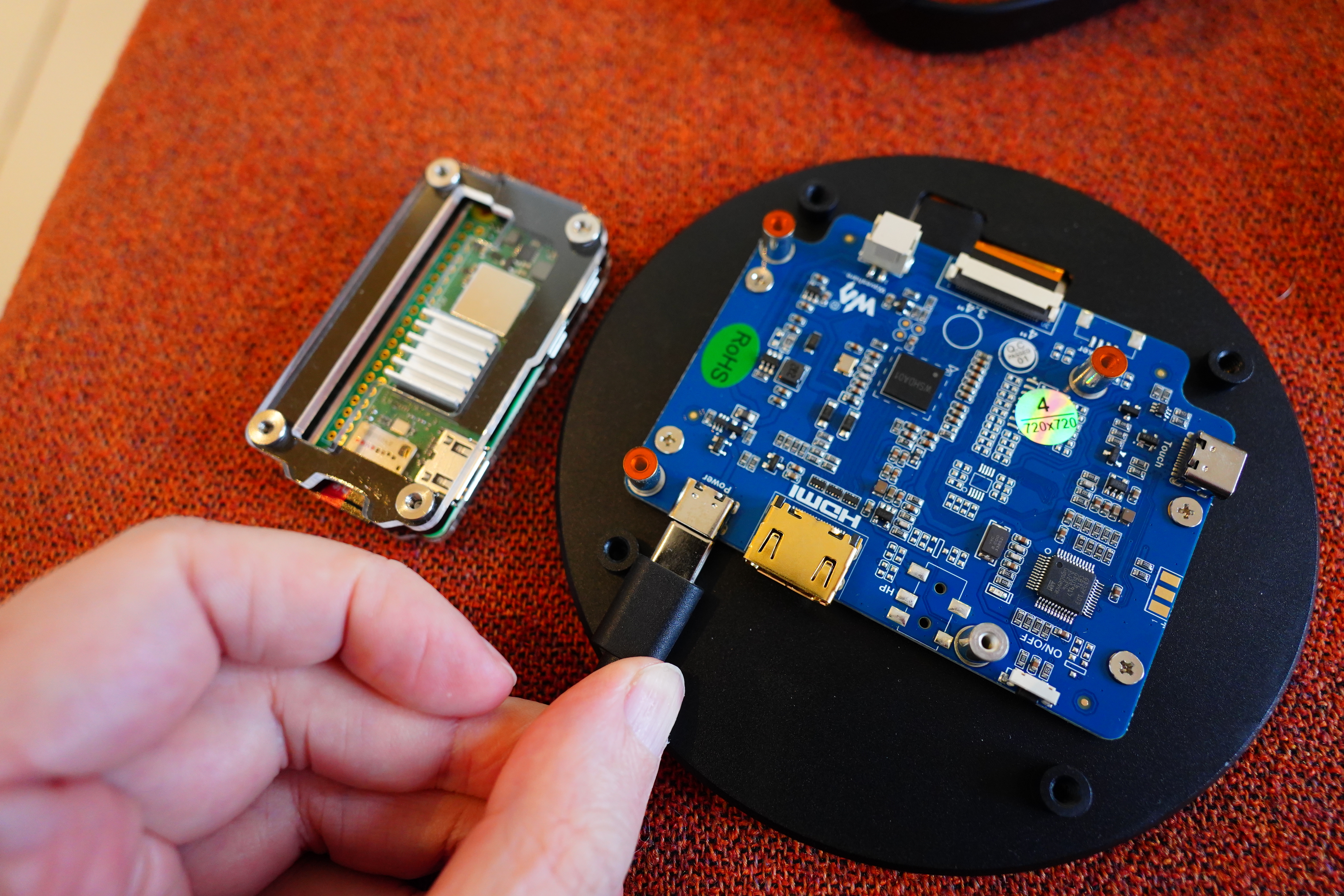
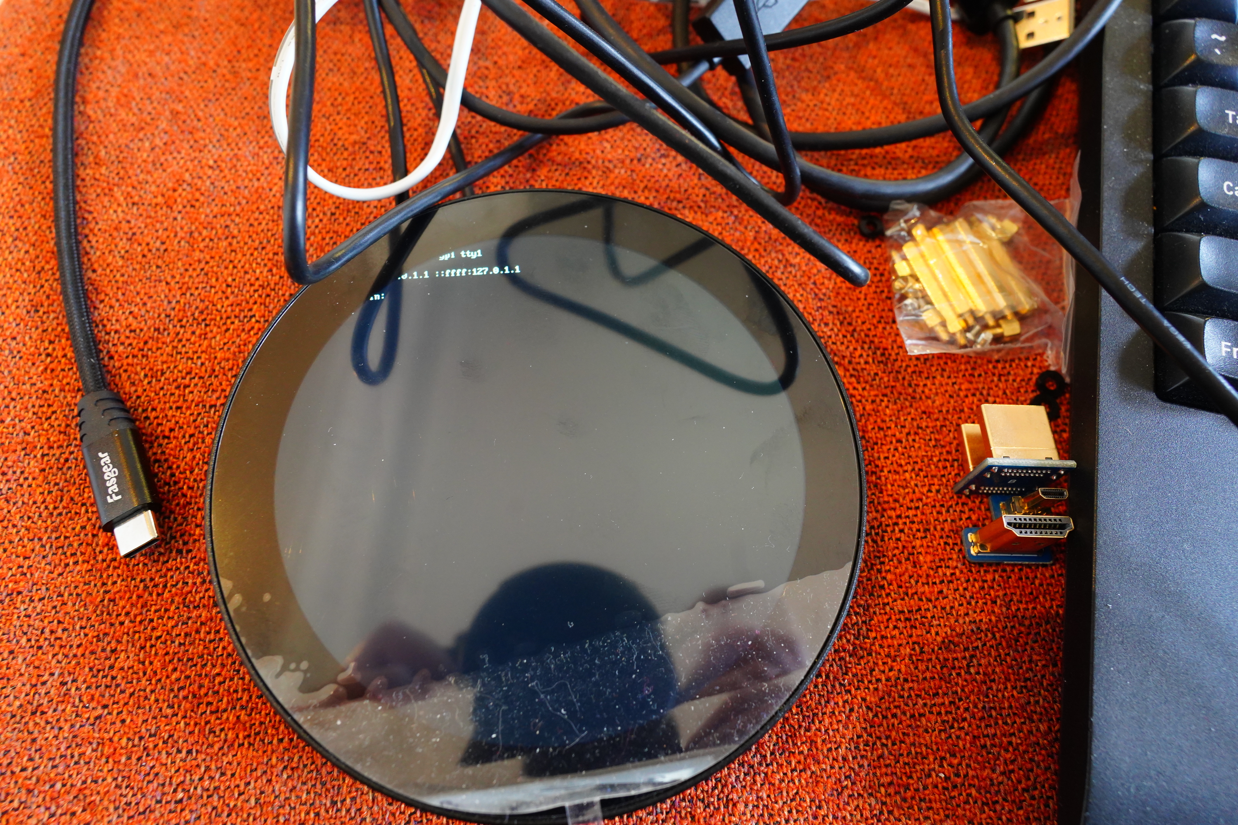
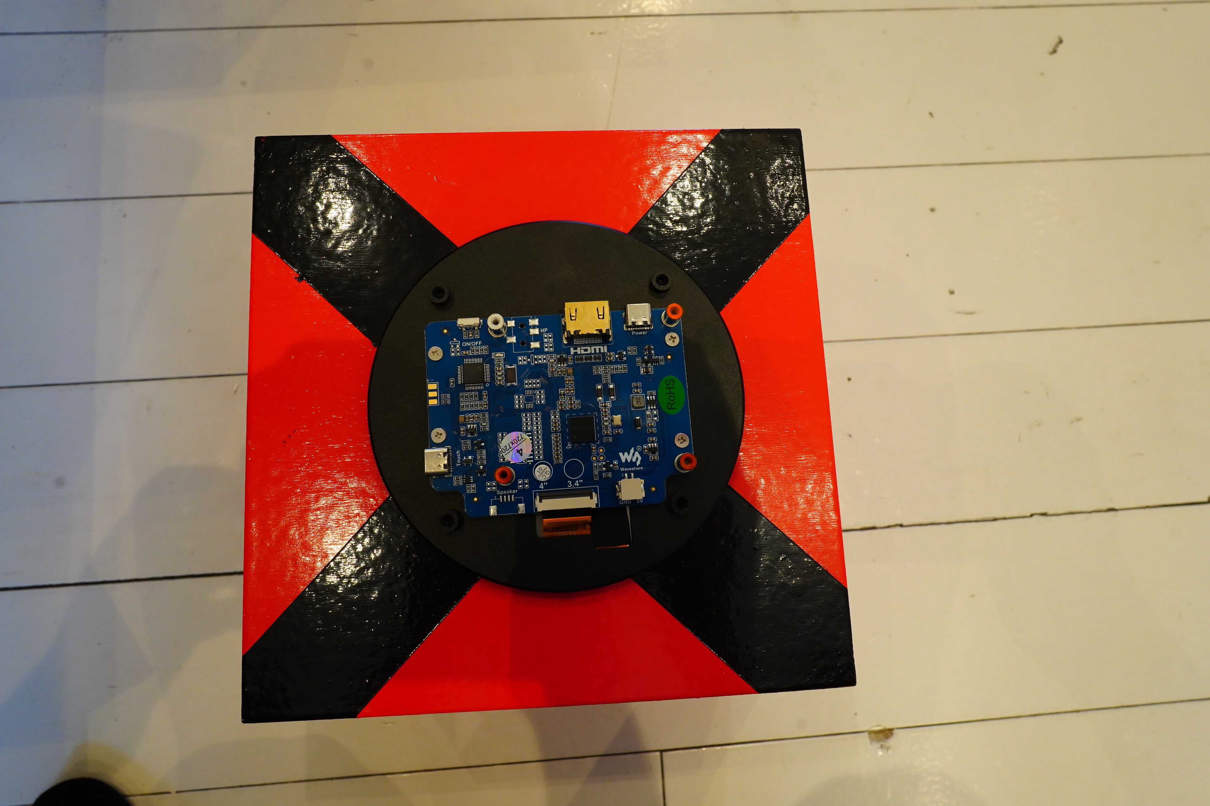
The connectors on the clock are side mounted…
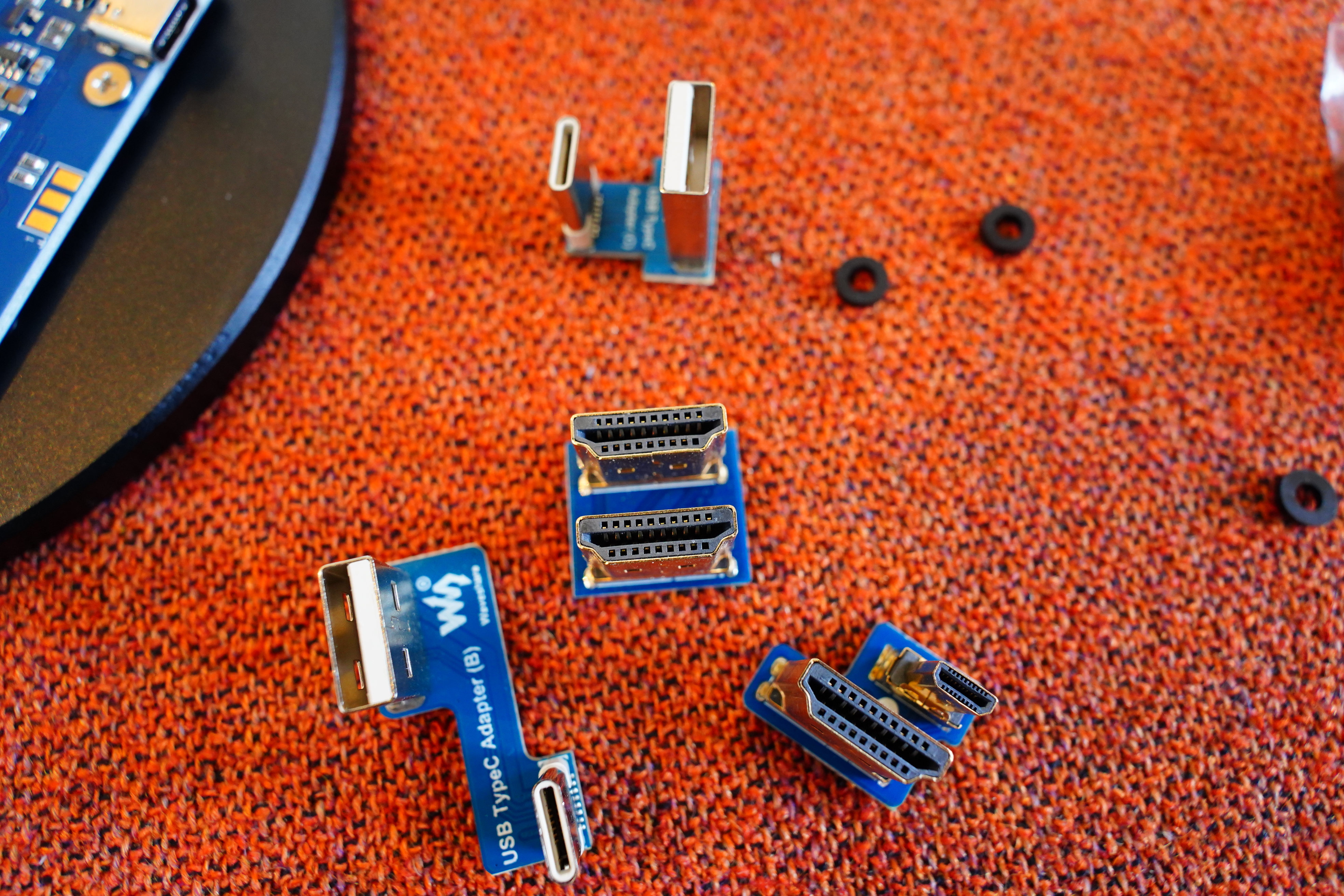
… but there’s all these adapters.
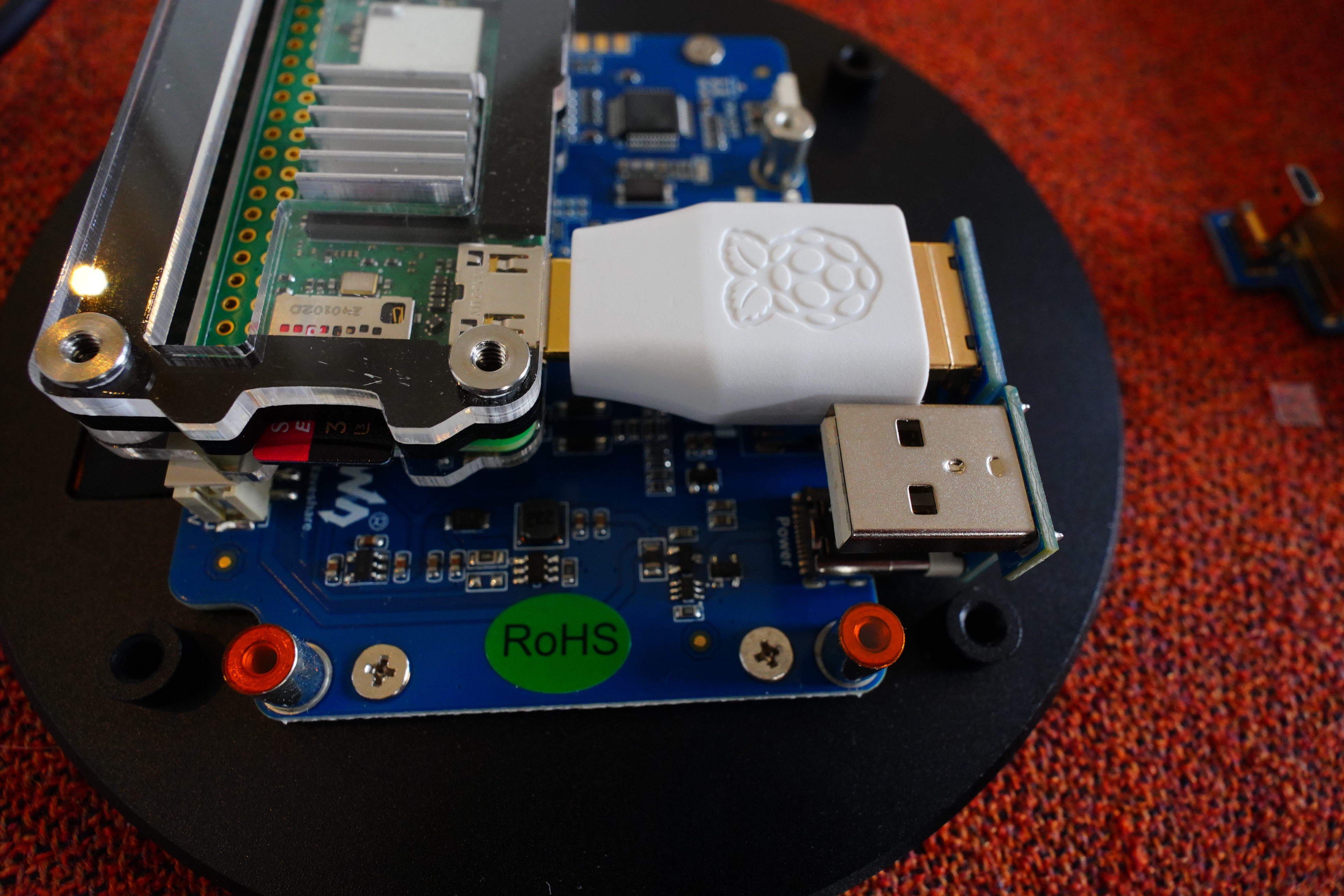
So… like this? But are there any Pis that have connectors in that configuration? I mean, it’s a full size HDMI and a USB A, side by side, and I can’t recall any that looked like that? I’m probably misremembering.
In any case, this doesn’t fit the Pi Zero at all, so I guess I’ll have to do, er, something… It would have been more useful if the adapters didn’t change the gender of the ports, but I guess that’s DIE for you.
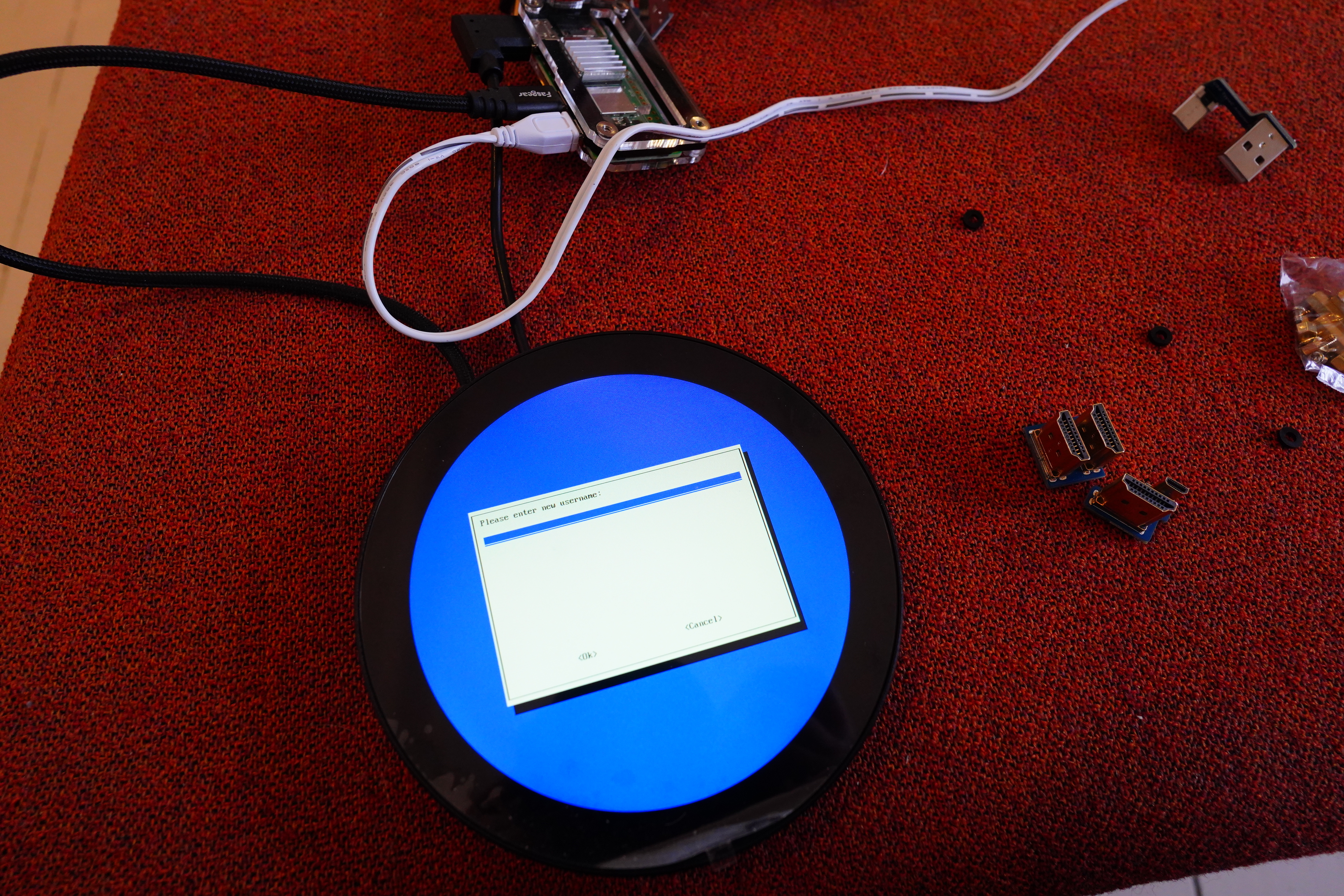
It’s alive!
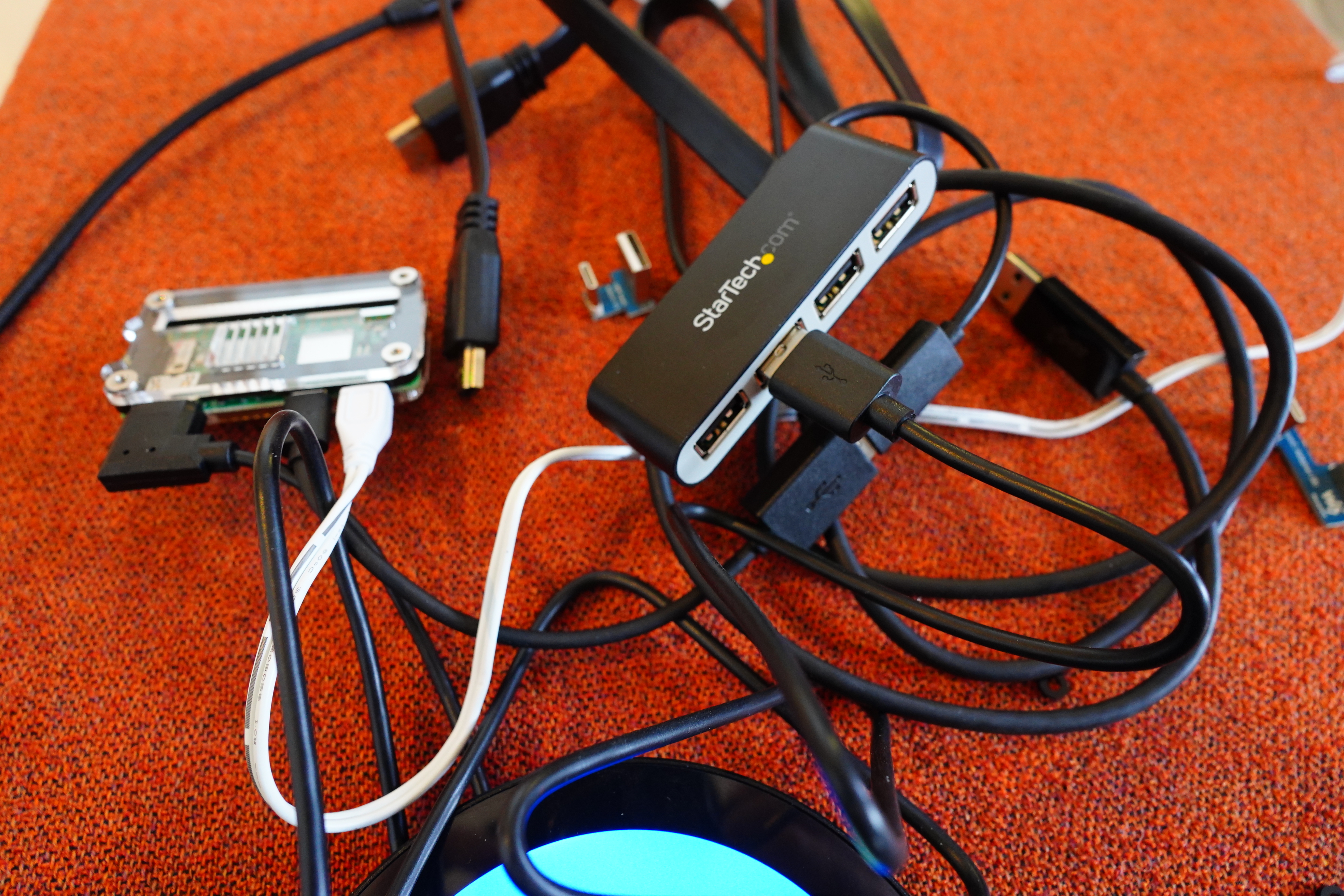
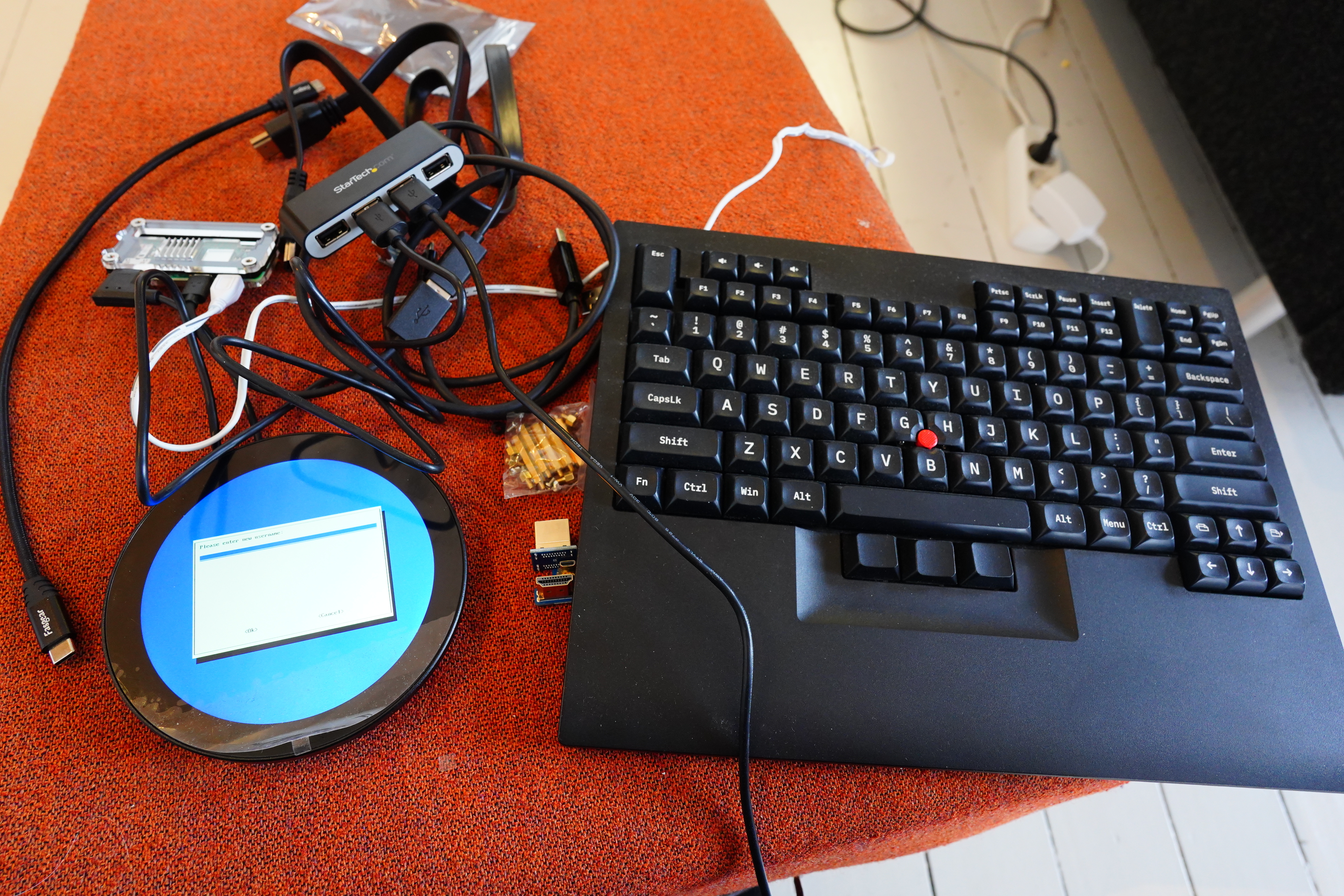
Oh, yeah, I need a keyboard while futzing around initially (before I get ssh up), so I need a third connector, and the Zero only has two, so it’s hubbin’ time.
See! LOOK HOW EASY.
I wondered how a round HDMI screen would work, but it (of course) just reports itself as a 720×720 screen, and then throws away all the pixels that are outside the circular screen.
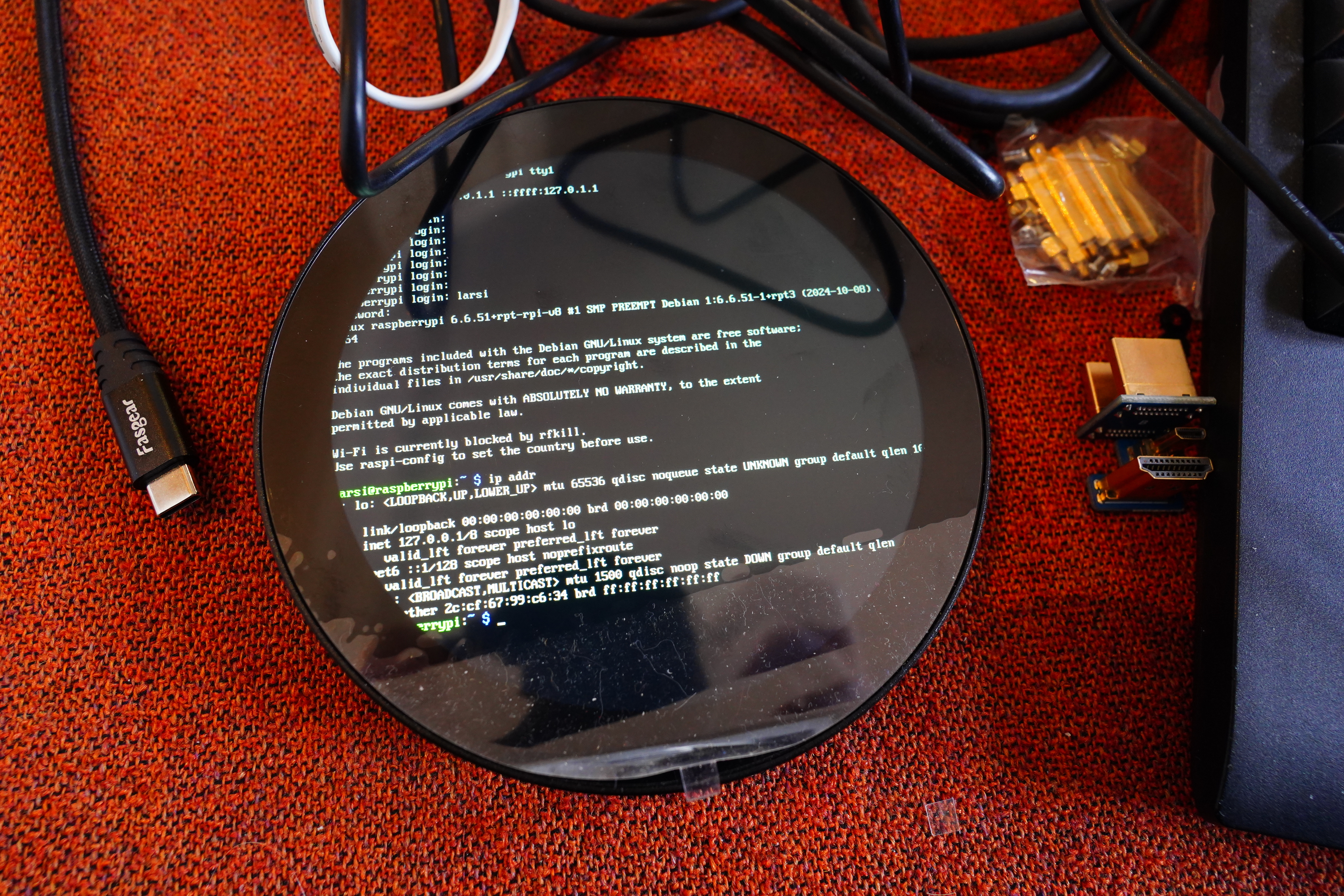
Which makes things, er, fun to work with, but I just need to get wifi and ssh up and running, and then I can do everything remotely.
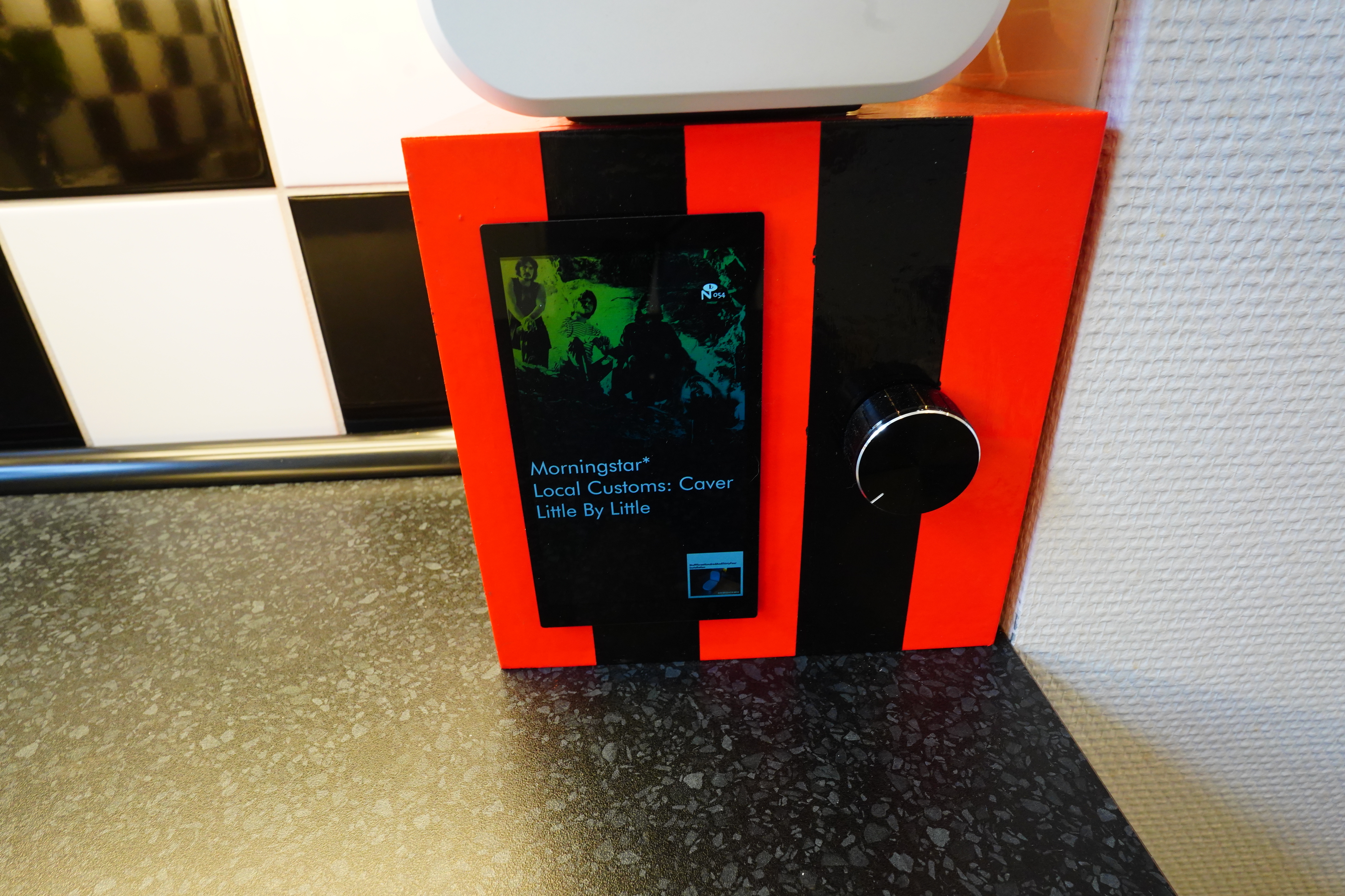
Tada!
But what’s that banding? Er…
This is what it looks like on my laptop screen.
dmesg says:
simple-framebuffer 1e876000.framebuffer: format=a8r8g8b8, mode=1280x720x32, linelength=5120
But fbset says:
fbset
mode “720×720”
geometry 720 720 720 720 16
timings 0 0 0 0 0 0 0
rgba 5/11,6/5,5/0,0/0
endmode
So the framebuffer is only 16 bits!? Whut?
The banding effect is kinda cool, but I wanted to figure out how to get 24/32 bit colour depth, and I failed.
I spent several hours googling, trying things, and rebooting: The decidedly most time consuming part of this project, and I still failed. Yes, I’ve tried all the video=HDMI-A-1:720x720M-32@60D kernel parameters and /boot/firmware/config.txt variations I can google myself to, but I failed.
So here’s my data: I’m using a Raspberry Pi Zero 2 W, running Raspbian 12 (bookworm) (aka. Raspberry Pi OS), and I’m using the standard framebuffer to display things, and I’m only getting 16 bits. Do you know how to fix this? (Only answer if you’ve fixed this yourself, not if you’ve googled an answer that doesn’t include all those three things.)
To display the image on the frambuffer, I first tried using fbi. It works, but it’s fiddly: It needs to run continuously — you can’t just call it to set the framebuffer (because then it’ll blink, for some reason or other), and it caches images, but only three of them. So you need to point it to three images, and then tell it to update every second, and then switch out the three images, and eh.
But I’d totally forgotten how simple frambuffers are: You just need to squirt RGB values to /dev/fb0, and that what appears on screen!
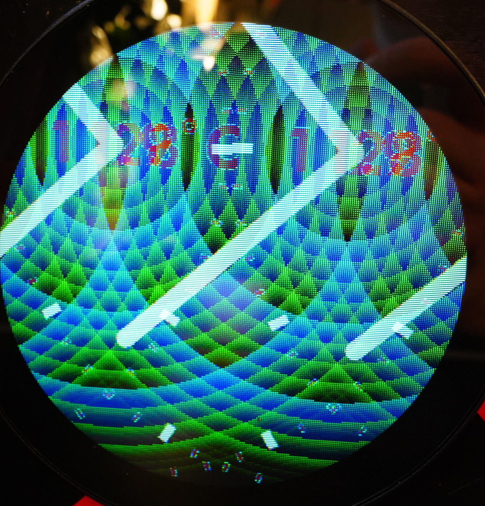
Er uhm. Oh yeah, it’s 16 bits, with 5 bits for blue, 6 for green and 5 for red… er..
convert ~/clock.png -type truecolor +flip -strip -define bmp:subtype=RGB565 bmp:- | tail -c $(( 720 * 720 * 16 / 8 )) > /dev/fb0
ImageMagick to the rescue! So I just convert the png to bmp and then chop off the header, and the squirt it to the device. High tech. (Code on Microsoft Github.)
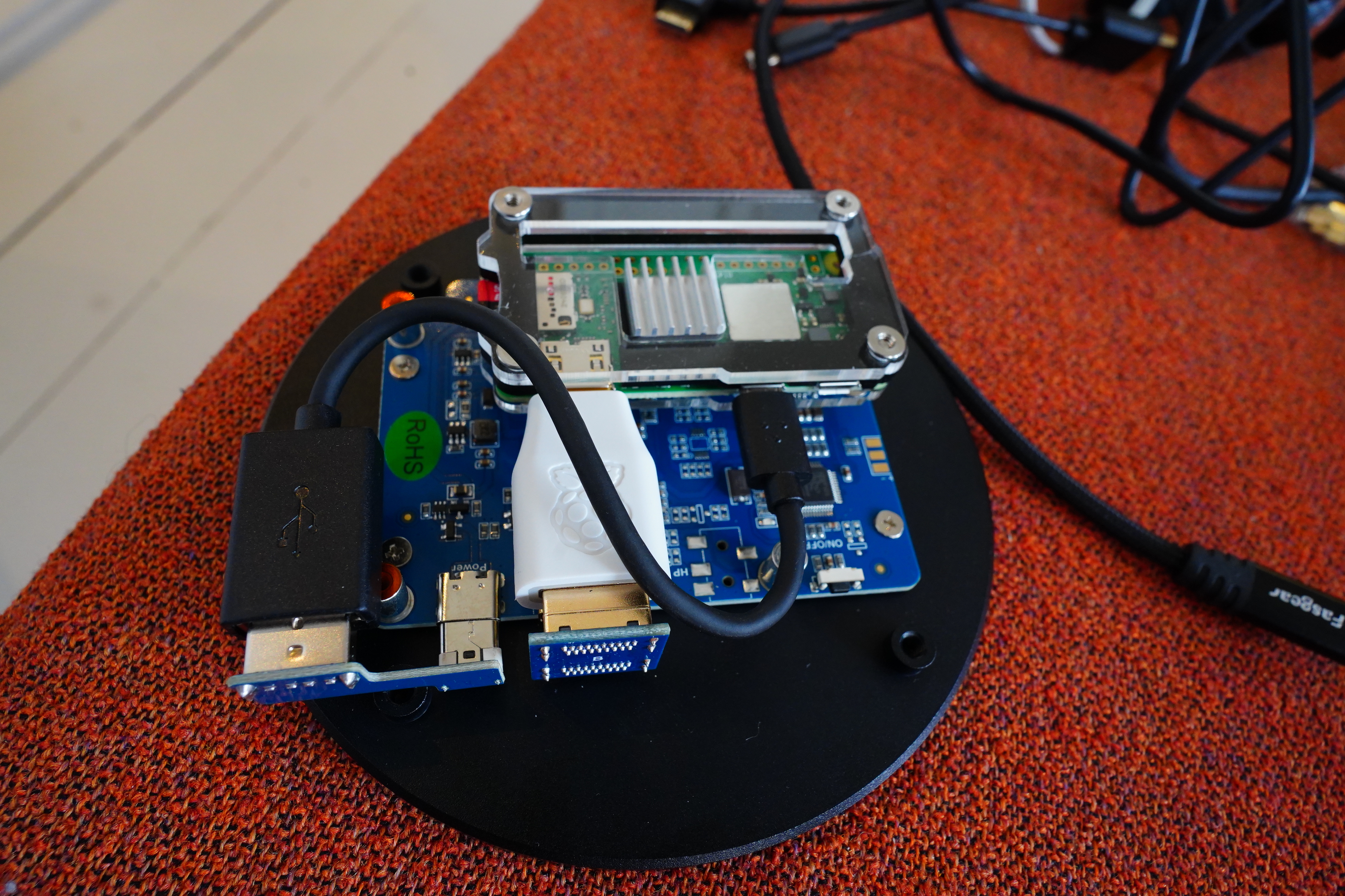
Anyway, back to the building the clock: I think I have to use the connectors, because just using normal side-mounted plugs will get in the way of the walls of the box.

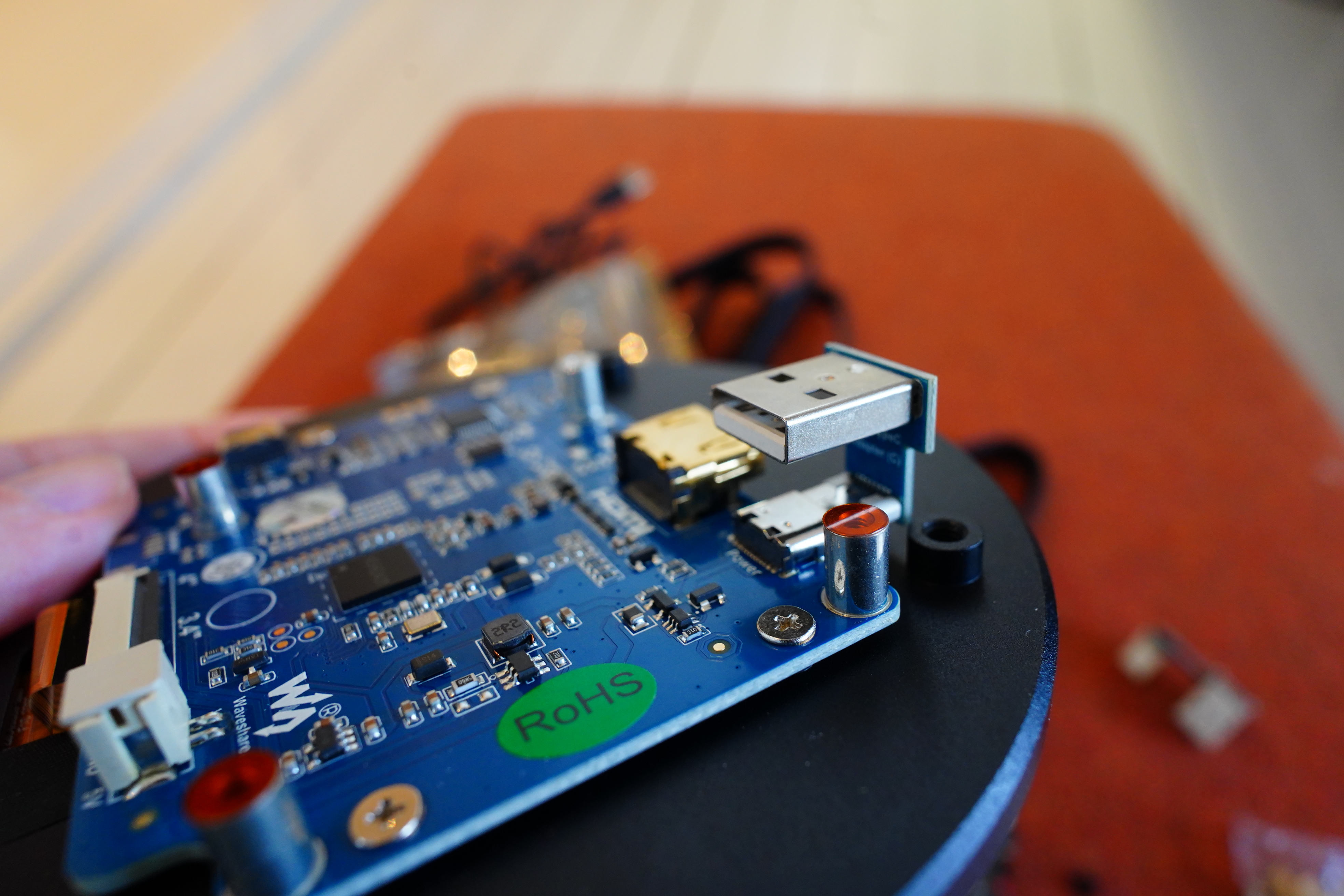
Look what I found in a drawer! That looks promising… and now for the power?
Yeah, this isn’t going to work…
But yes! The snakey thing fits!
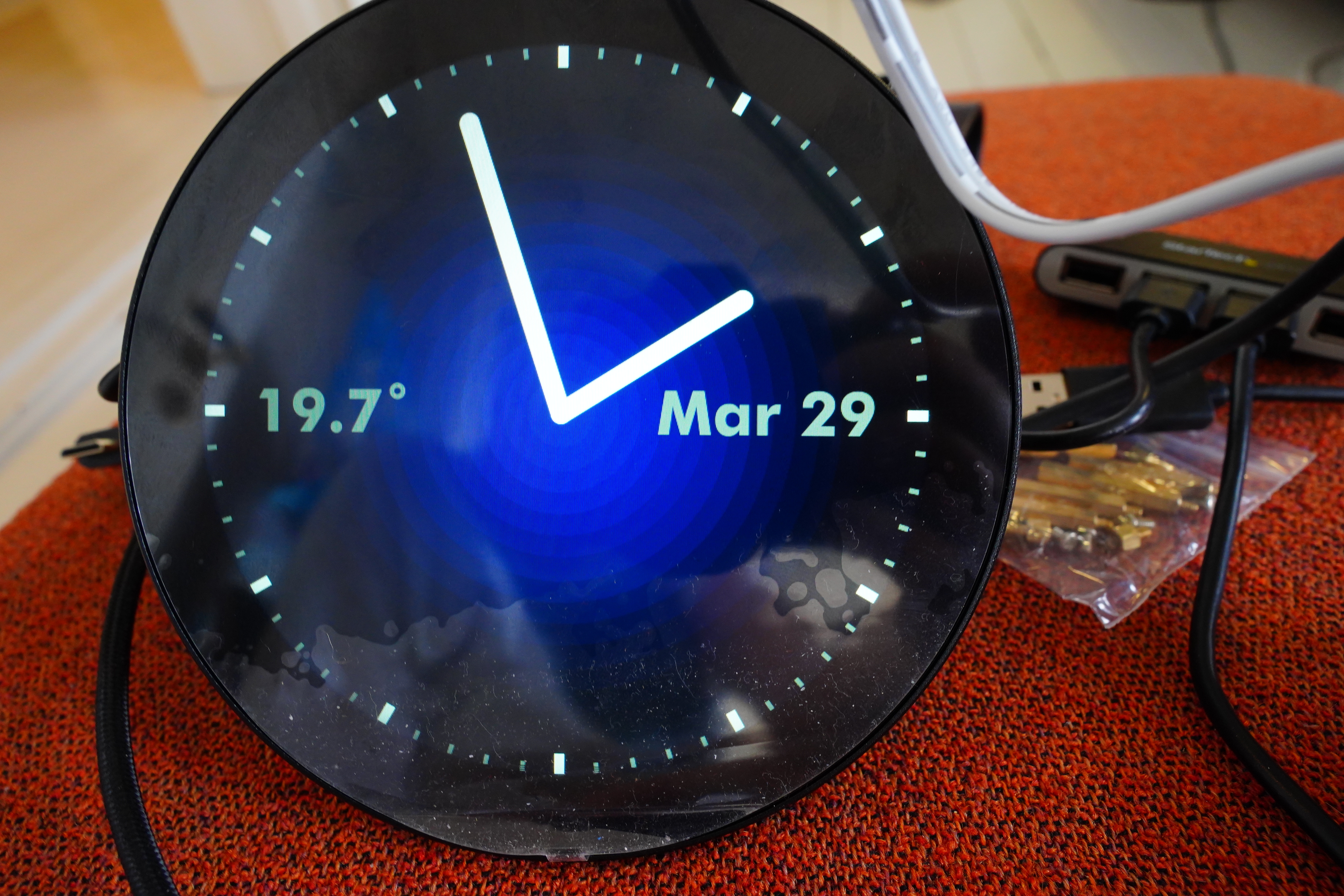
One last test… OH NO I”VE GOT AN OFF BY ONE ERROR IN THE MONTH no I didn’t. It’s not showing the months, but instead the day of the week — in French. Oh la la, trés a la mode.
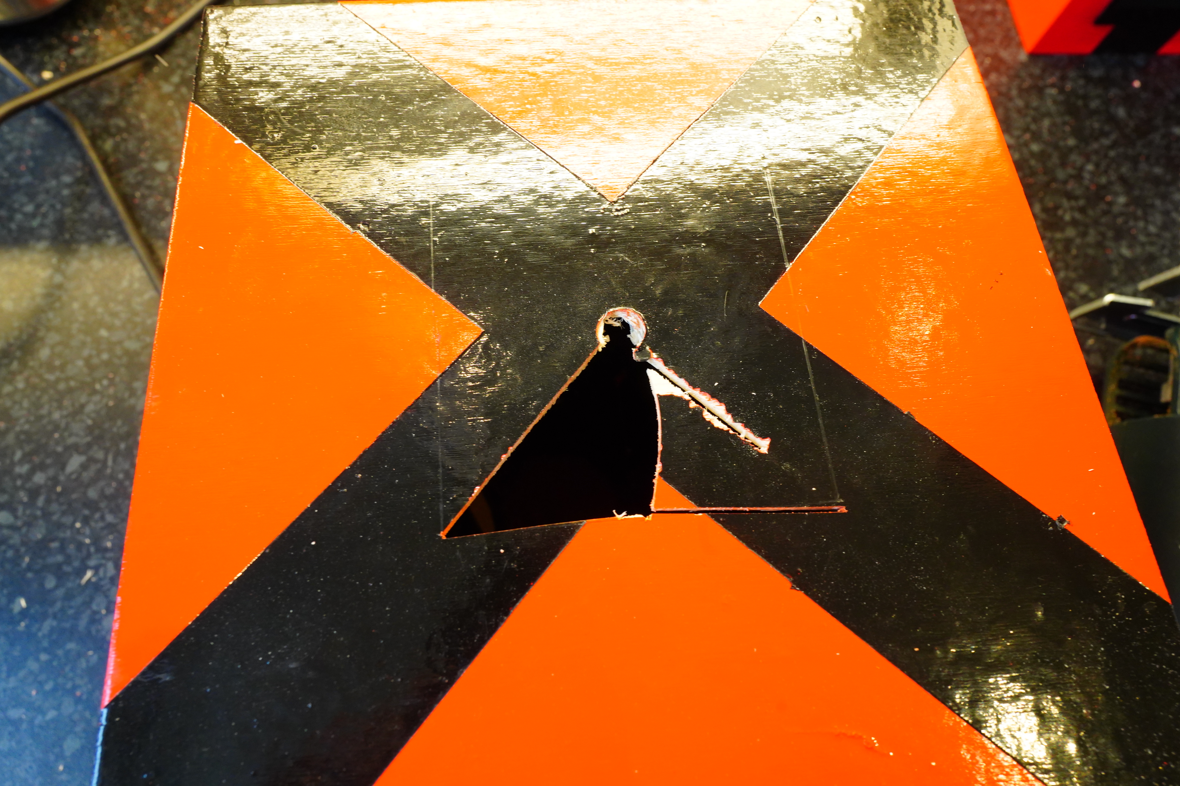
OK, it’s cutting time. But not this box.
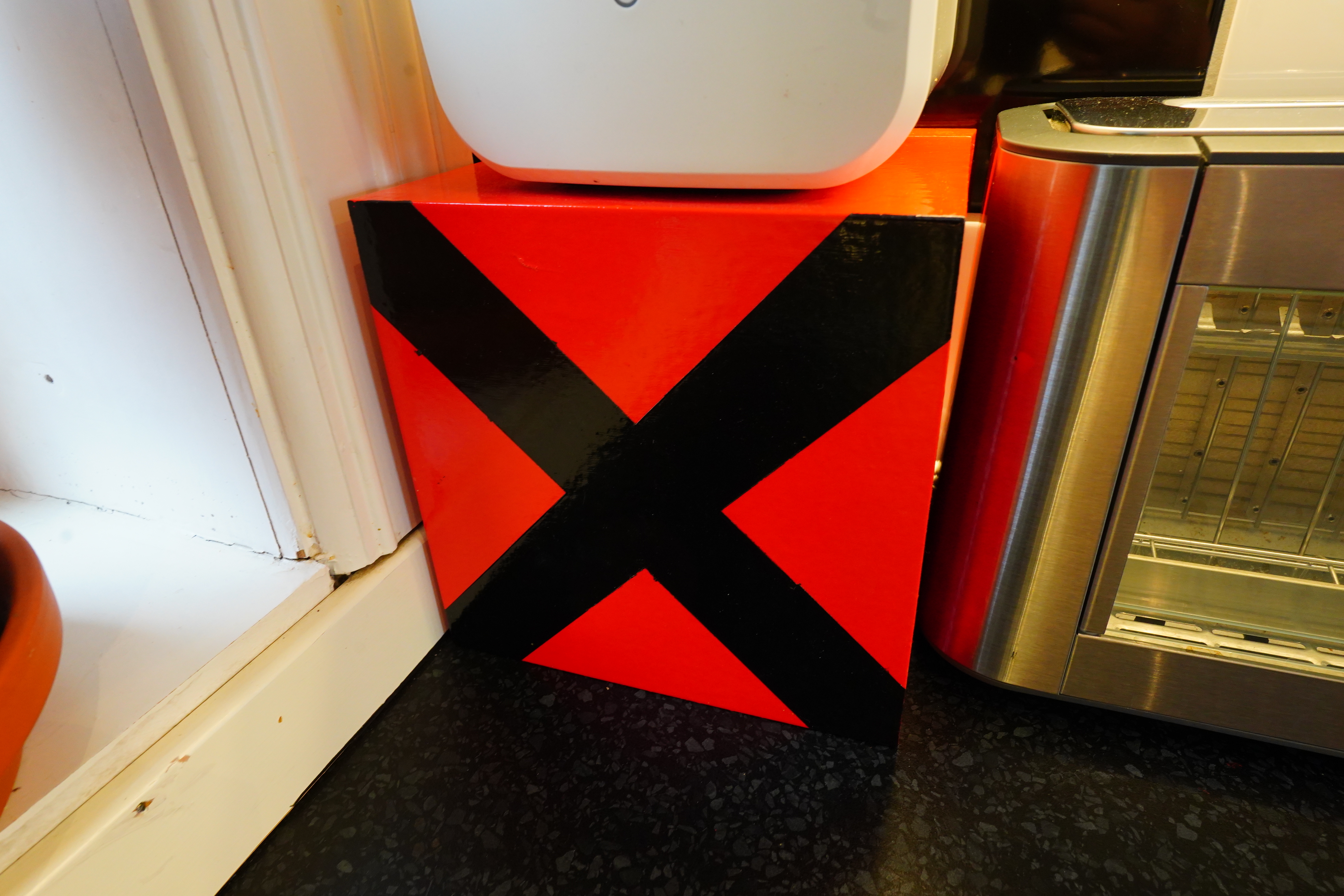
This box.
See?

So it’s 80mm in width (the bits that need to go into the box).
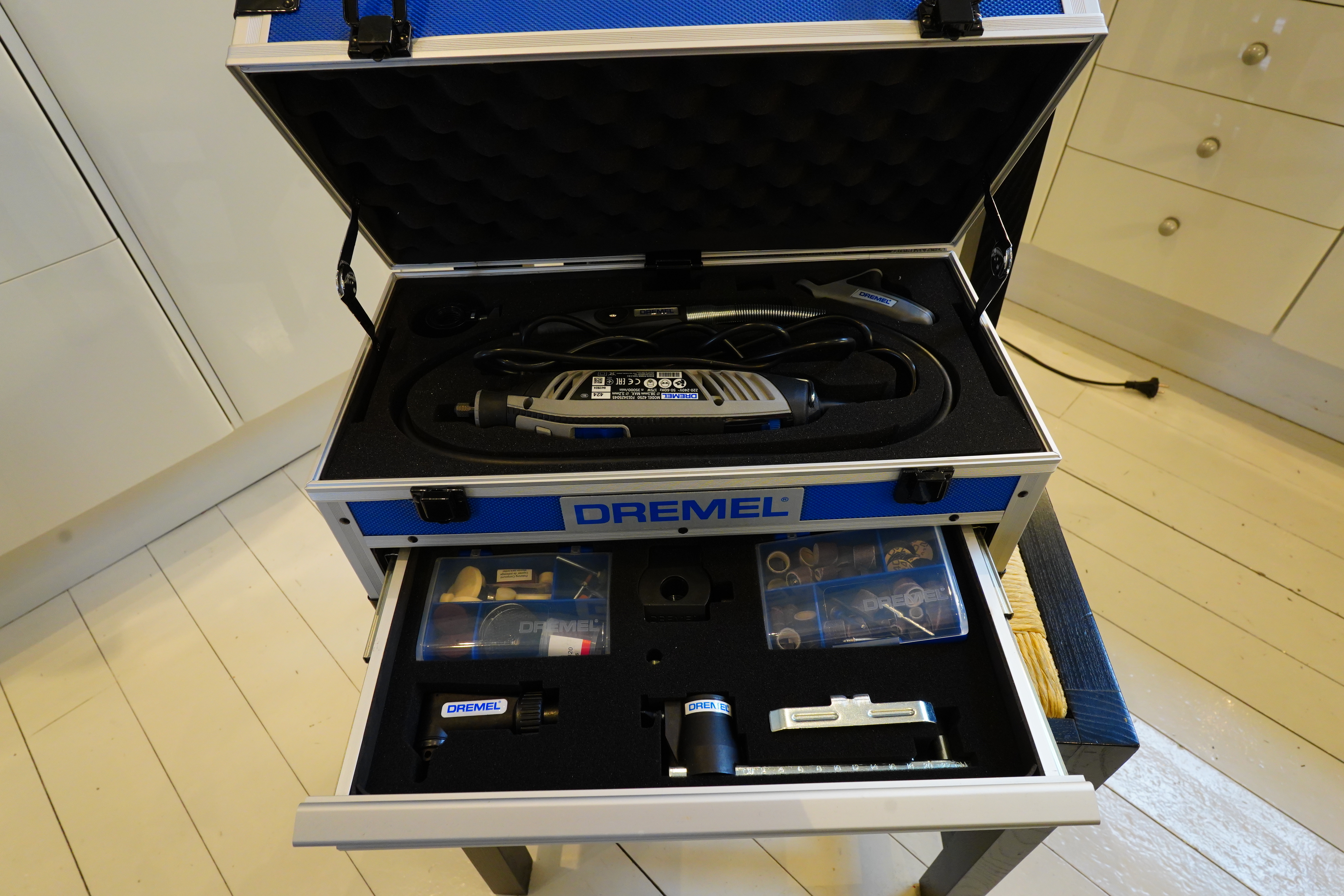
I bought a Dremel set to do the cutting this time, but er I forgot to read the instruction manual, and I don’t wanna do that now, so let’s just use a drill and a jigsaw.
Drill baby.
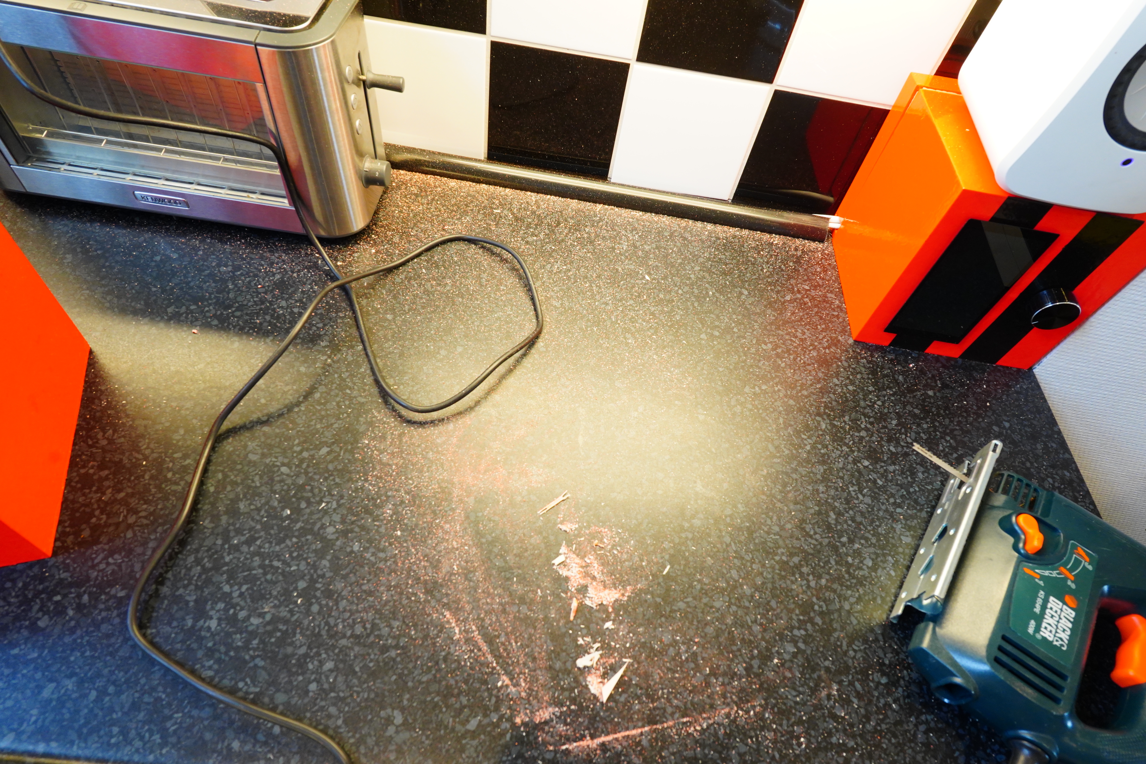
OOPS! I totally didn’t notice that the blade on this new battery jigsaw is super duper coarse. It says “Fast Wood” — it rips the box to shreds. And I seem to not have bought any appropriate blades for this jigsaw…
Fortunately, I still have my old mains powered jigsaw.
Behold! The difference!
Cut cut cut…
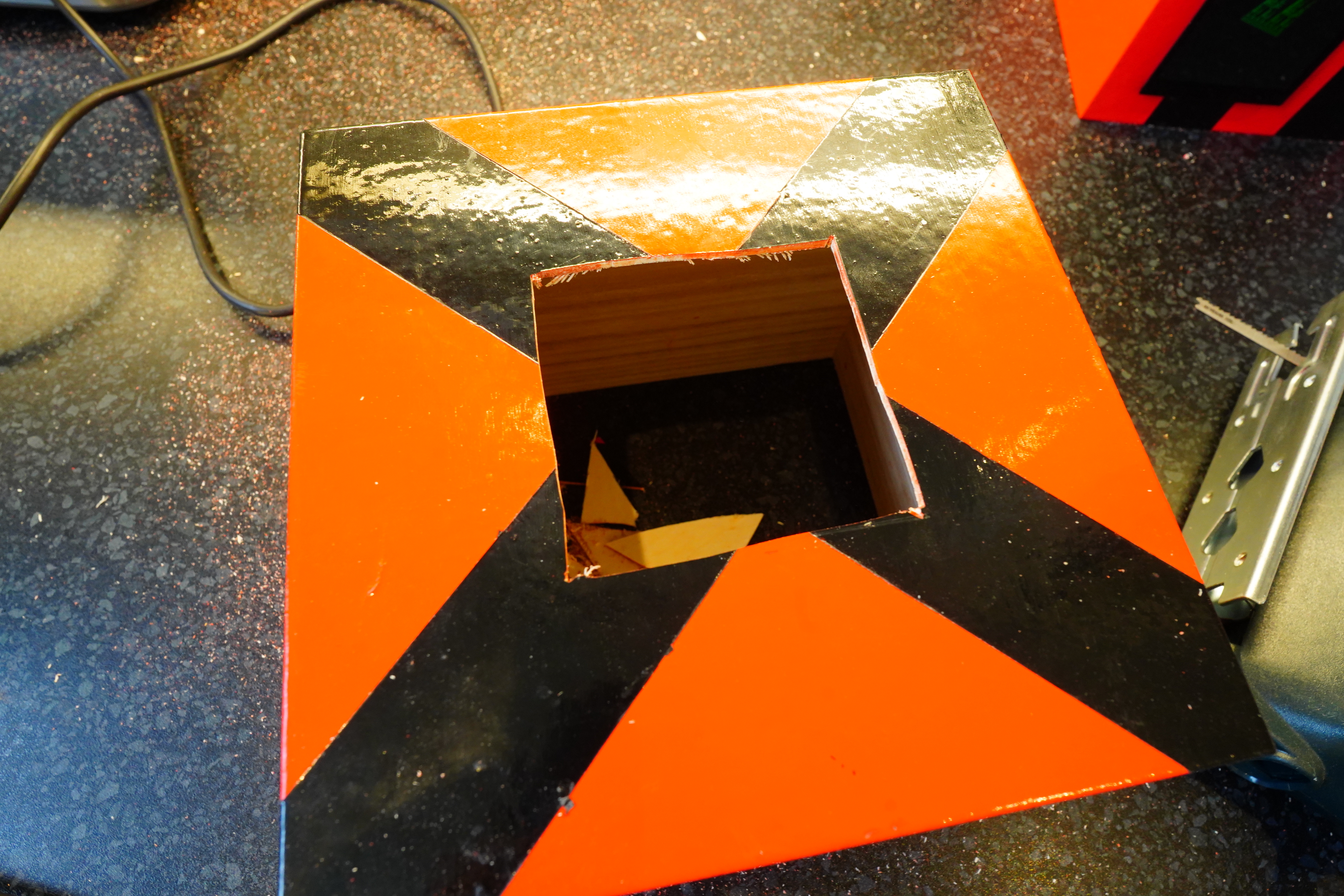
Done! You’ve never seen such even and straight cuts ever!
And I adhered to that age old saying “measure once, cut twice”. I don’t know why it’s better to cut twice, but who am I to argue against passed-down wisdom like that.
(What I’m saying is that the width was actually 83mm, not 80mm.)
So dirty!
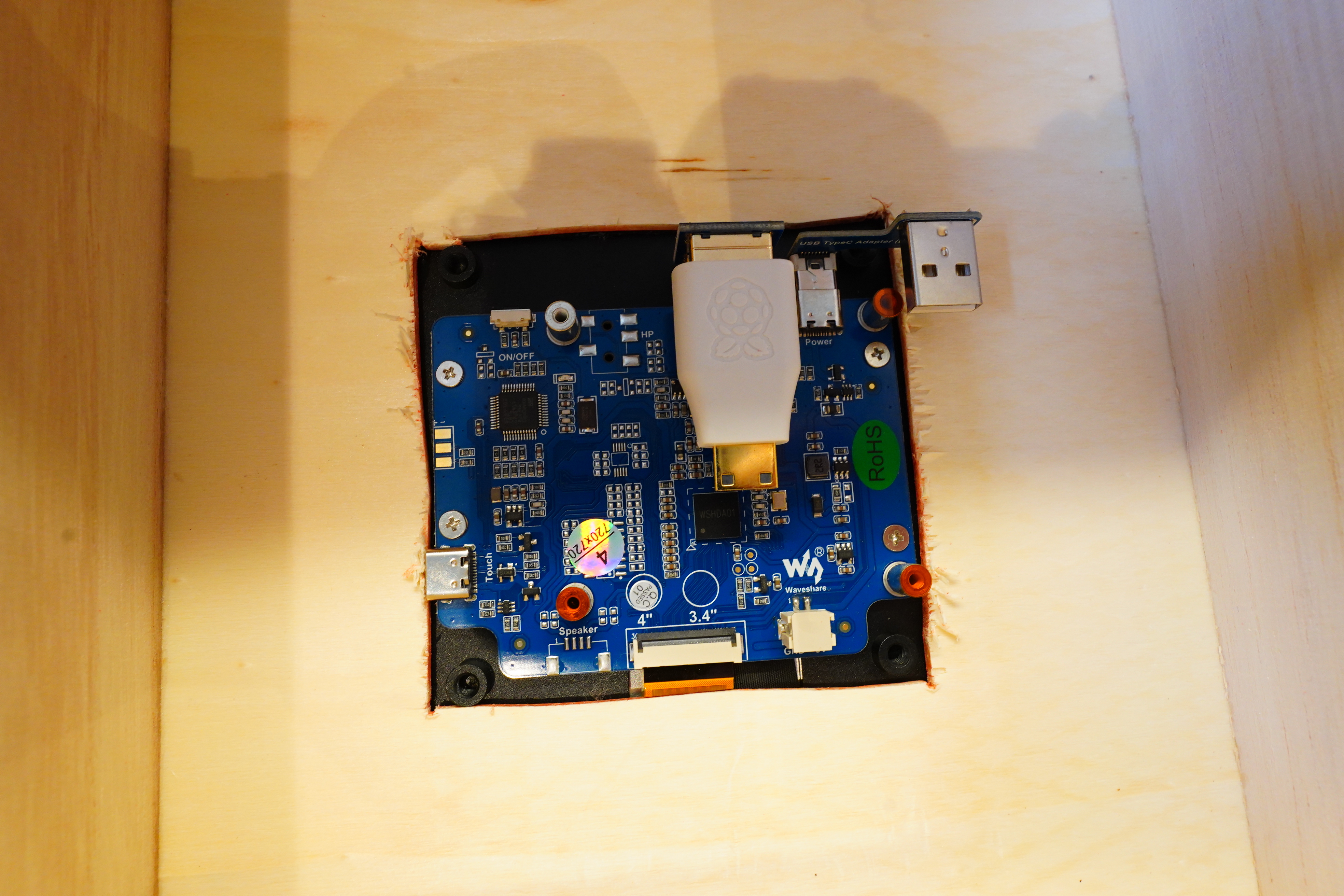
Yes, everything fits! Actually, I could probably have used the side-mounted plugs — I forgot how thin the walls of this box is.
Pluggeti-plug… Nice and snug.
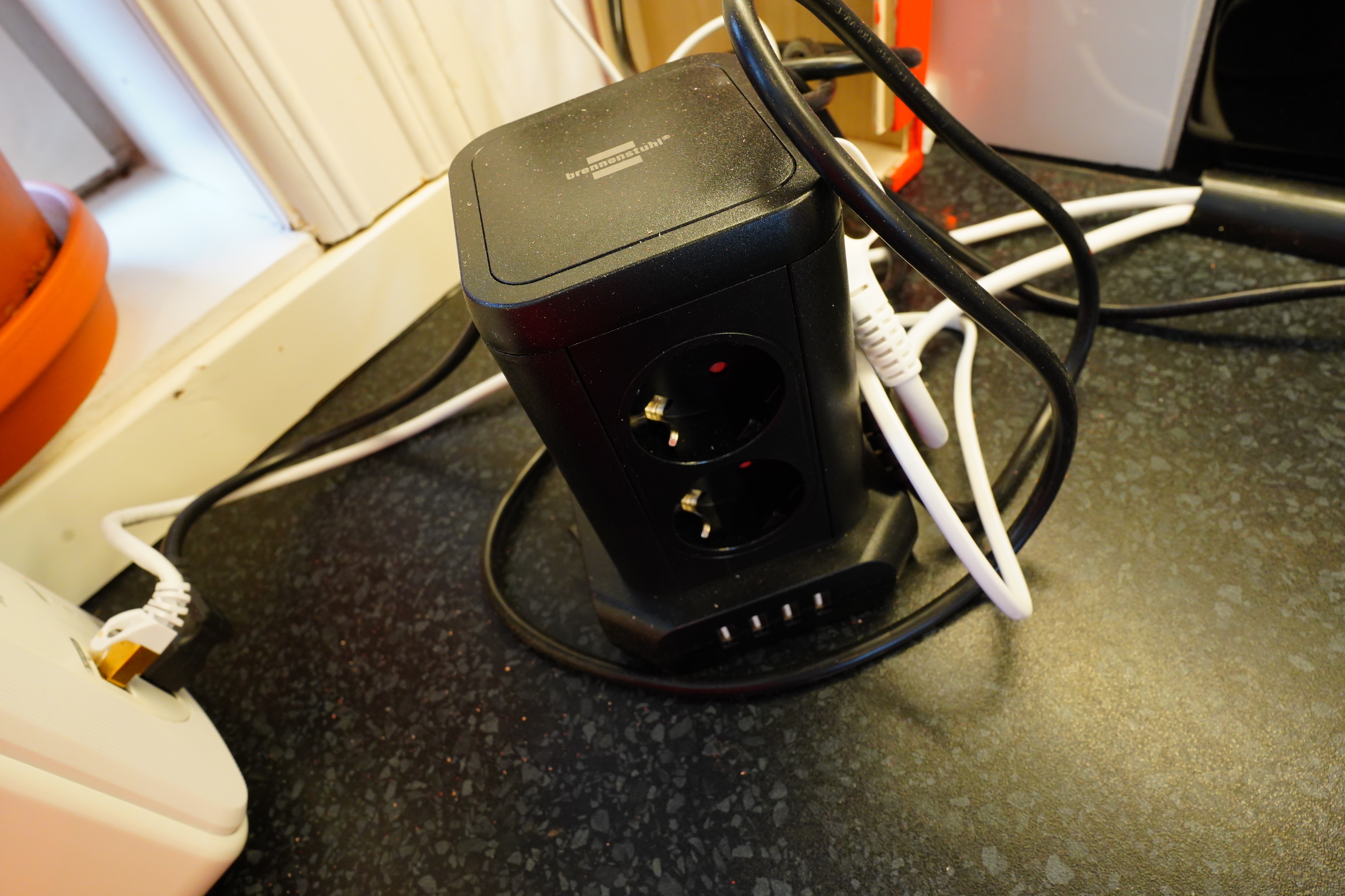
Yeah, this also goes into the box — power to various other things here, and USB power for the Pi.
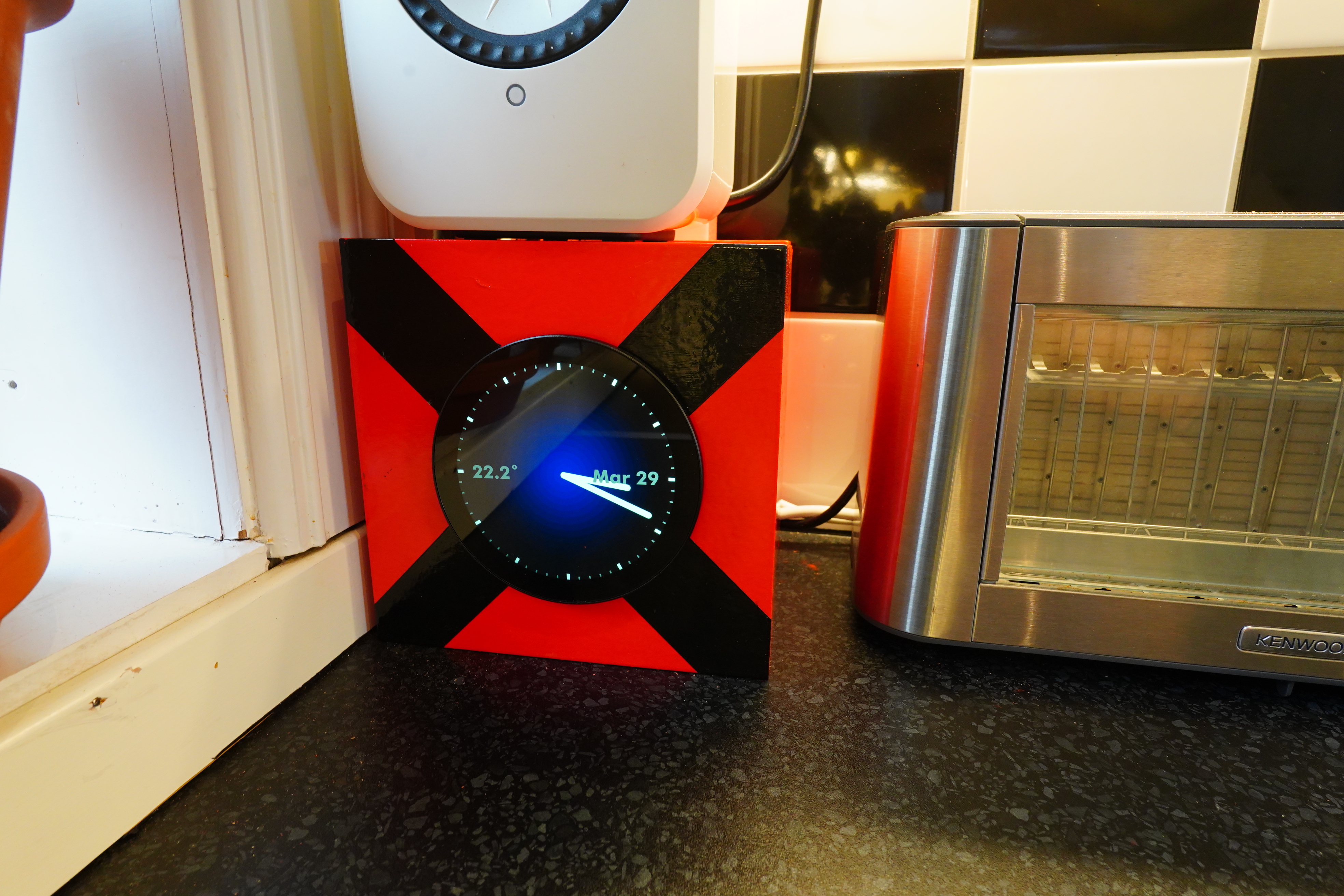
IT WORKS!!!
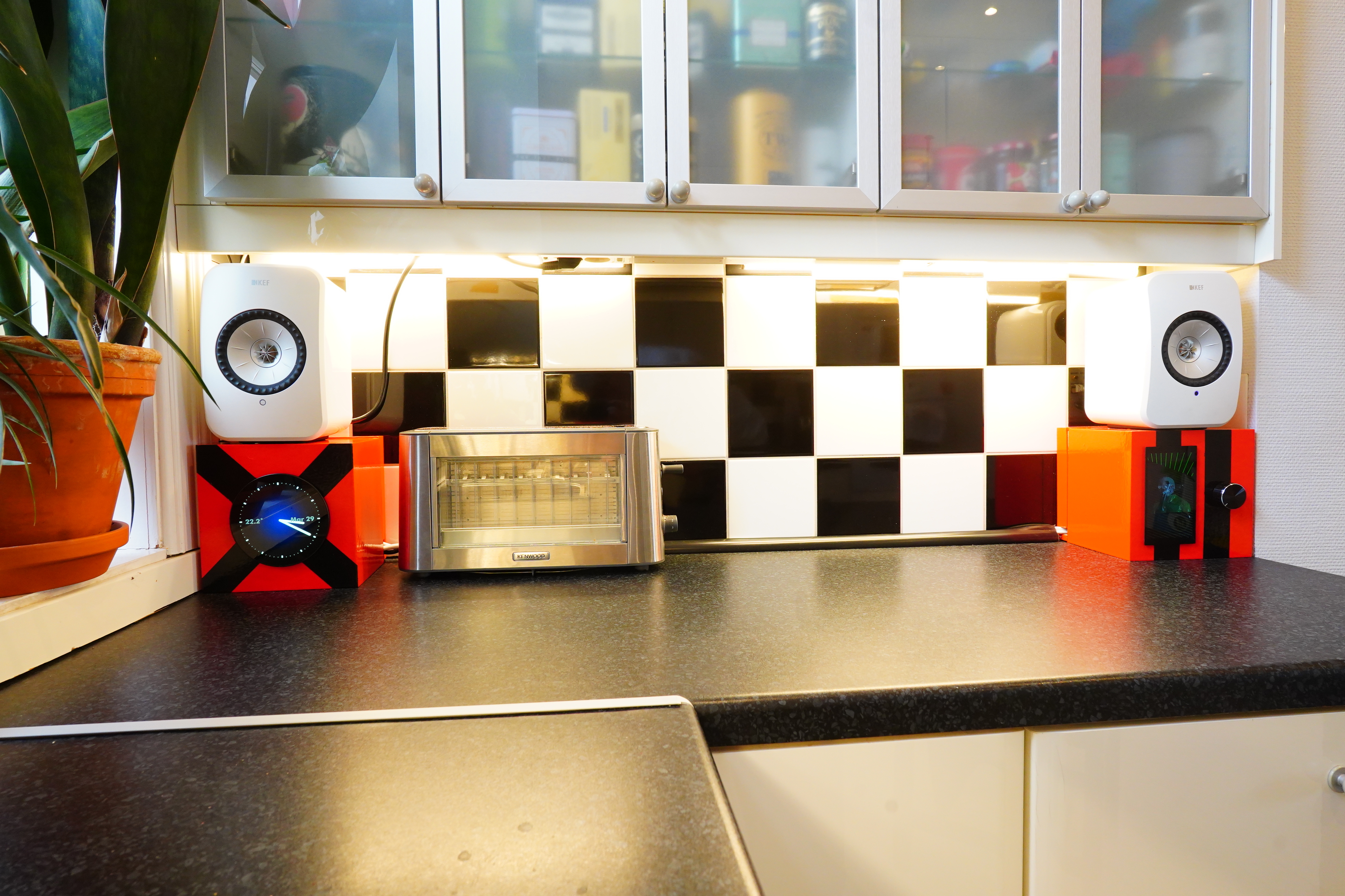
See? So much better than just buying a clock.
I had a single RPI3 for like…years now. I still haven’t done anything useful with it.
I had a voice assistant for a while, that I made “from scratch”, but since I didn’t use it that much, the Pi is sitting in a box.
Wish I had as many ideas for small devices as you do 😅
Btw, in French, you should write “très à la mode”, or you’ll loose 2 points for spelling.
*hangs head in eternal shame*